Page 367 - Advances in Renewable Energies and Power Technologies
P. 367

340    CHAPTER 10 Scalar and Vector Control of Induction Motor


                         4.2 SELECTION OF THE REGULATORS
                         The regulators used are PI type whose transfer functions are given by:
                                                         K p ð1 þ s p sÞ
                                                  RðsÞ¼                               (10.12)
                                                            s p s
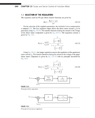
                            For the selection of the regulator parameters, the method of zeros compensation
                         is adopted [24]. The flux regulator output allows the direct stator current i sd to be
                         generated, using Eq. (10.10). The transfer function relating the current to the voltage
                         of the direct stator component is given by Eq. (10.13). The regulation scheme is
                         given by Fig. 10.3.
                                                                 1

                                                                   m 2
                                                               r s þ
                                                    i sd ðsÞ       l r s r
                                            H 1 ðsÞ¼     ¼                            (10.13)
                                                   v sd ðsÞ       k s

                                                                        s
                                                           1 þ
                                                                    m 2
                                                                r s þ
                                                                    l r s r
                            Using Eq. (10.11), the torque regulation ensures the regulation of the quadrature
                         stator current i sq . The transfer function relating the current to the voltage of the quad-
                         rature stator component is given by Eq. (10.14) with its principle described by
                         Fig. 10.4:
                                                                 1

                                                                   m 2
                                                               r s þ
                                                    i sq ðsÞ       l r s r
                                            H 2 ðsÞ¼     ¼                            (10.14)
                                                    v sq ðsÞ      k s
                                                                        s
                                                           1 þ
                                                                    m 2
                                                                r s þ
                                                                    l r s r
                                                       Flux            m
                                           +                          —
                                            -        regulator        1 + τ s
                                                                         r
                         FIGURE 10.3
                         Principle of flux regulation.


                                                               i
                                                       PI       sq      m
                                           +                       C em = p —  ϕ r  i sq
                                            -                           l r


                         FIGURE 10.4
                         Principle of the torque regulation.
   362   363   364   365   366   367   368   369   370   371   372