
Page 95 - Amphibionics : Build Your Own Biologically Inspired Robot
P. 95
Amphibionics 04 3/24/03 8:23 AM Page 74
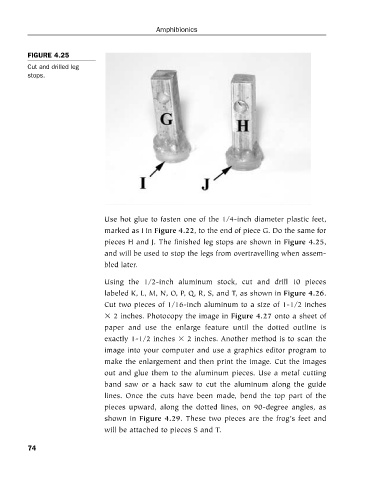
FIGURE 4.25
Cut and drilled leg
stops. Amphibionics
Use hot glue to fasten one of the 1/4-inch diameter plastic feet,
marked as I in Figure 4.22, to the end of piece G. Do the same for
pieces H and J. The finished leg stops are shown in Figure 4.25,
and will be used to stop the legs from overtravelling when assem-
bled later.
Using the 1/2-inch aluminum stock, cut and drill 10 pieces
labeled K, L, M, N, O, P, Q, R, S, and T, as shown in Figure 4.26.
Cut two pieces of 1/16-inch aluminum to a size of 1-1/2 inches
2 inches. Photocopy the image in Figure 4.27 onto a sheet of
paper and use the enlarge feature until the dotted outline is
exactly 1-1/2 inches 2 inches. Another method is to scan the
image into your computer and use a graphics editor program to
make the enlargement and then print the image. Cut the images
out and glue them to the aluminum pieces. Use a metal cutting
band saw or a hack saw to cut the aluminum along the guide
lines. Once the cuts have been made, bend the top part of the
pieces upward, along the dotted lines, on 90-degree angles, as
shown in Figure 4.29. These two pieces are the frog’s feet and
will be attached to pieces S and T.
74