
Page 111 - An Introduction to Microelectromechanical Systems Engineering
P. 111
90 MEM Structures and Systems in Industrial and Automotive Applications
Bondpad
{100} Si P-type diffused
diaphragm piezoresistor Metal conductors
N-type
epitaxial
R
R 2 1 layer
R 3
P-type
{111} substrate
and frame
Anodically
bonded
Etched cavity Pyrex substrate
Backside port
(a)
R
1 R 2
V bridge
R 3 R 4 V out
(b)
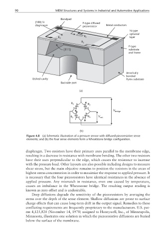
Figure 4.8 (a) Schematic illustration of a pressure sensor with diffused piezoresistive sense
elements; and (b) the four sense elements form a Wheatstone bridge configuration.
diaphragm. Two resistors have their primary axes parallel to the membrane edge,
resulting in a decrease in resistance with membrane bending. The other two resistors
have their axes perpendicular to the edge, which causes the resistance to increase
with the pressure load. Other layouts are also possible including designs to measure
shear stress, but the main objective remains to position the resistors in the areas of
highest stress concentration in order to maximize the response to applied pressure. It
is necessary that the four piezoresistors have identical resistances in the absence of
applied pressure. Any mismatch in resistance, even one caused by temperature,
causes an imbalance in the Wheatstone bridge. The resulting output reading is
known as zero offset and is undesirable.
Deep diffusions degrade the sensitivity of the piezoresistors by averaging the
stress over the depth of the sense element. Shallow diffusions are prone to surface
charge effects that can cause long-term drift in the output signal. Remedies to these
conflicting requirements are frequently proprietary to the manufacturers. U.S. pat-
ent 4,125,820 (November 14, 1978) assigned to Honeywell, Inc., of Minneapolis,
Minnesota, illustrates one solution in which the piezoresistive diffusions are buried
below the surface of the membrane.