
Page 142 - An Introduction to Microelectromechanical Systems Engineering
P. 142
Actuators and Actuated Microsystems 121
liquids from 3M Chemicals of St. Paul, Minnesota. Their boiling point ranges
from 56° to 250ºC, and they exhibit large temperature coefficients of expansion
(~ 0.13% per degree Celsius). They are also electrically insulating and have a high
dielectric constant. Clearly, the choice of control liquid determines the actuation
temperature and, correspondingly, the power consumption and switching times of
the valve.
The NO-1500 Fluistor normally open gas valve provides proportional control
of the flow rate for noncorrosive gases. The flow rate ranges from 0.1 sccm up to
1,500 sccm. The maximum inlet supply pressure is 690 kPa (100 psig) , the switch-
4
ing time is typically 0.5s, and the corresponding average power consumption is 500
mW. The NC-1500 Fluistor is a normally closed gas valve (see Figure 4.33) with
similar pressure and flow ratings, but its switching response is 1s and it consumes
1.5W. Because the Fluistor relies on the absolute temperature—rather than a differ-
ential temperature—of the control liquid for actuation, the valve cannot operate at
elevated ambient temperatures. Consequently, the Fluistor is rated for operation
from 0° to 55ºC. The normally closed valve measures approximately 6 mm × 6 mm
× 2 mm and is packaged inside a TO-8 can with two attached tubes (see Chapter 8).
The packaging is further discussed in Chapter 8.
U.S. Patent 4,966,646 (October 30, 1990) describes the basic fabrication steps
for a normally open valve; however, the fabrication details of a normally closed
valve are not publicly available. The following process delineates the general steps
to fabricate a normally closed valve. The features in the intermediate silicon layer
are fabricated by etching both sides of the wafer in potassium hydroxide. The
front-side etch forms the cavity that will later be filled with the actuation liquid. The
etch on the bottom side forms the fulcrum as well as the valve plug. Accurate timing
and a well-controlled etch rate of both etches ensure the formation of the thin
Pyrex
Resistive
heater
Silicon
Fluorinert
filled cavity
Pyrex
Pivot point
Outlet port
{111} plane Diaphragm
(b)
(a)
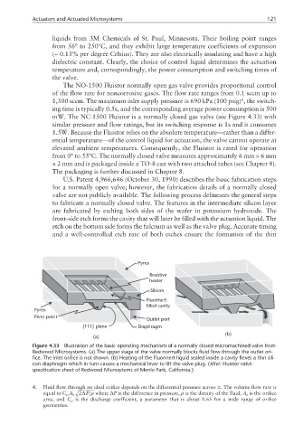
Figure 4.33 Illustration of the basic operating mechanism of a normally closed micromachined valve from
Redwood Microsystems. (a) The upper stage of the valve normally blocks fluid flow through the outlet ori-
fice. The inlet orifice is not shown. (b) Heating of the Fluorinert liquid sealed inside a cavity flexes a thin sili-
con diaphragm which in turn causes a mechanical lever to lift the valve plug. (After: Fluistor valve
specification sheet of Redwood Microsytems of Menlo Park, California.)
4. Fluid flow through an ideal orifice depends on the differential pressure across it. The volume flow rate is
equal to CA 2∆ P ρ where ∆P is the difference in pressure, ρ is the density of the fluid, A is the orifice
D 0 0
area, and C is the discharge coefficient, a parameter that is about 0.65 for a wide range of orifice
D
geometries.