
Page 141 - An Introduction to Microelectromechanical Systems Engineering
P. 141
120 MEM Structures and Systems in Industrial and Automotive Applications
Micromachined Valve from Redwood Microsystems
Early development of this valve took place in the mid 1980s at Stanford University
[44]. Redwood Microsystems was founded shortly thereafter with the objective of
commercializing the valve. The actuation mechanism of either normally open or
3
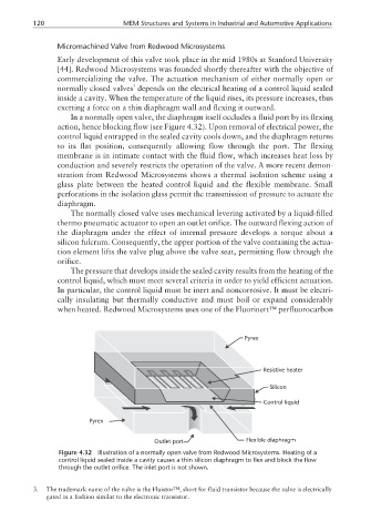
normally closed valves depends on the electrical heating of a control liquid sealed
inside a cavity. When the temperature of the liquid rises, its pressure increases, thus
exerting a force on a thin diaphragm wall and flexing it outward.
In a normally open valve, the diaphragm itself occludes a fluid port by its flexing
action, hence blocking flow (see Figure 4.32). Upon removal of electrical power, the
control liquid entrapped in the sealed cavity cools down, and the diaphragm returns
to its flat position, consequently allowing flow through the port. The flexing
membrane is in intimate contact with the fluid flow, which increases heat loss by
conduction and severely restricts the operation of the valve. A more recent demon-
stration from Redwood Microsystems shows a thermal isolation scheme using a
glass plate between the heated control liquid and the flexible membrane. Small
perforations in the isolation glass permit the transmission of pressure to actuate the
diaphragm.
The normally closed valve uses mechanical levering activated by a liquid-filled
thermo pneumatic actuator to open an outlet orifice. The outward flexing action of
the diaphragm under the effect of internal pressure develops a torque about a
silicon fulcrum. Consequently, the upper portion of the valve containing the actua-
tion element lifts the valve plug above the valve seat, permitting flow through the
orifice.
The pressure that develops inside the sealed cavity results from the heating of the
control liquid, which must meet several criteria in order to yield efficient actuation.
In particular, the control liquid must be inert and noncorrosive. It must be electri-
cally insulating but thermally conductive and must boil or expand considerably
when heated. Redwood Microsystems uses one of the Fluorinert™ perfluorocarbon
Pyrex
Resistive heater
Silicon
Control liquid
Pyrex
Outlet port Flexible diaphragm
Figure 4.32 Illustration of a normally open valve from Redwood Microsystems. Heating of a
control liquid sealed inside a cavity causes a thin silicon diaphragm to flex and block the flow
through the outlet orifice. The inlet port is not shown.
3. The trademark name of the valve is the Fluistor™, short for fluid transistor because the valve is electrically
gated in a fashion similar to the electronic transistor.