
Page 146 - An Introduction to Microelectromechanical Systems Engineering
P. 146
Actuators and Actuated Microsystems 125
Upper controlling orifice
Inlet port at p in Electrical contact
Top wafer
Middle wafer p out p in p in p out flow
Bottom wafer path
Slider Actuator ribs
Outlet port at p out
Thin recess
(a)
Inlet port
Top wafer
Electrical contacts
Outline of outlet port in
Slider
bottom wafer
Slot Fixed hinge
Middle wafer
Frame
Actuator ribs
Movable hinge
and pushrod Deep recess
Bottom wafer
Outlet port
Thin recess
(b)
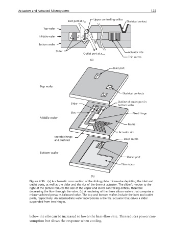
Figure 4.36 (a) A schematic cross section of the sliding plate microvalve depicting the inlet and
outlet ports, as well as the slider and the ribs of the thermal actuator. The slider’s motion to the
right of the picture reduces the size of the upper and lower controlling orifices, therefore
decreasing the flow through the valve. (b) A rendering of the three silicon wafers that comprise a
micromachined pressure-balanced valve. The top and bottom wafers include the inlet and outlet
ports, respectively. An intermediate wafer incorporates a thermal actuator that drives a slider
suspended from two hinges.
below the ribs can be increased to lower the heat-flow rate. This reduces power con-
sumption but slows the response when cooling.