
Page 435 - Analog and Digital Filter Design
P. 435
432 Analog and Digital Filter Design
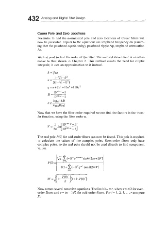
Cauer Pole and Zero Locations
Formulae to find the normalized pole and zero locations of Cauer filters will
now be presented. Inputs to the equations are stopband frequency us (assum-
ing that the passband equals unity), passband ripple Ap, stopband attenuation
As.
We first need to find the order of the filter. The method shown here is an alter-
native to that shown in Chapter 2. This method avoids the need for elliptic
integrals; it uses an approximation to it instead.
100.IAr -1
= 100.1.” -1
Now that we have the filter order required we can find the factors in the trans-
fer function, using the filter order n.
The real pole P(0) for odd-order filters can now be found. This pole is required
to calculate the values of the complex poles. Even-order filters only have
complex poles, so the real pole should not be used directly to find component
values.
Now comes several recursive equations. The limit is i = r, where r = nl2 for even-
order filters and r = (n - 1)/2 for odd-order filters. For i = 1, 2, 3, . . . r compute
z.