
Page 103 - Analytical Electrochemistry 2d Ed - Jospeh Wang
P. 103
88 CONTROLLED-POTENTIAL TECHNIQUES
hydrodynamic voltammograms. These can be obtained by making repeated ¯ow
injections of the analyte solution while recording the current at different potentials.
The resulting voltammogram has a characteristic wave (sigmoidal) shape. Although
it is common to operate the detector on the limiting-current plateau region, a
lowering of the operating potential (to the rising portion of the wave) can be used to
improve the selectivity and lower the detection limit. Comparison of hydrodynamic
voltammograms for the sample and standard solutions can provide important
qualitative information.
Depending on their conversion ef®ciency, electrochemical detectors can be
divided into two categories: those that electrolyze only a negligible fraction (0.1±
5%) of the electroactive species passing through the detector (amperometric
detectors), and those for which the conversion ef®ciency approaches 100% (coulo-
metric detectors). Unfortunately, the increased conversion ef®ciency of the analyte is
accompanied by a similar increase for the electrolyte (background) reactions, and no
lowering of detection limits is realized.
3-6.2 Cell Design
A wide range of cell designs have been used for electrochemical monitoring of
¯owing streams. The cell design must ful®ll the requirements of high signal-to-noise
ratio, low dead volume, well-de®ned hydrodynamics, small ohmic drop, and ease of
construction and maintenance (polishing). In addition, the reference and counter
electrodes should be located on the downstream side of the working electrode, so
that reaction products at the counter electrode or leakage from the reference
electrode do not interfere with the working electrode.
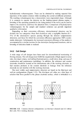
The most widely used amperometric detectors are based on the thin-layer and
wall-jet con®gurations (Figure 3-22). The thin-layer cell relies on a thin layer of
solution that ¯ows parallel to the planar electrode surface, which is imbedded in a
FIGURE 3-22 Common detector con®gurations: (a) thin-layer (channel) and (b) wall-jet
¯ow cells. WE working electrode.