
Page 104 - Analytical Electrochemistry 2d Ed - Jospeh Wang
P. 104
3-6 FLOW ANALYSIS 89
rectangular channel. The ¯ow channel is formed by two plastic blocks pressing a
thin Te¯on gasket, which de®nes the very small dead volume ( 1 mL). In the wall-jet
design, the stream ¯ows from a nozzle perpendicularly onto a ¯at electrode surface
(the wall), and then spreads radially over the surface. The electrode diameter is
signi®cantly larger than that of the nozzle inlet. Since the jet remains intact up to
quite large inlet±electrode separations, it is possible to employ large-volume wall-jet
detectors that offer decreased sensitivity to the properties of the mobile phase and
simpli®ed fabrication.
It is possible to employ detectors with solutions ¯owing over a static mercury
drop electrode or a carbon-®ber microelectrode, or to use ¯ow-through electrodes,
with the electrode simply an open tube or porous matrix. The latter can offer
complete electrolysis, that is coulometric detection. The extremely small dimensions
of ultramicroelectrodes (discussed in Section 4-5.4) offer the advantages of ¯ow rate
independence (and hence a low noise level) and operation in nonconductive mobile
phases (such as those of normal-phase chromatography or supercritical ¯uid
chromatography). Ultramicroelectrodes can also greatly bene®t modern microse-
paration techniques such as open-tubular liquid chromatography or capillary zone
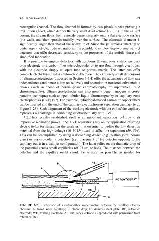
electrophoresis (CZE) (57). For example, cylindrical-shaped carbon or copper ®bers
can be inserted into the end of the capillary electrophoresis separation capillary (e.g.,
Figure 3-23). Such alignment of the working electrode with the end of the capillary
represents a challenge in combining electrochemistry with CZE.
CZE has recently established itself as an important separation tool due to its
impressive separation power. Since CZE separations rely on the application of strong
electric ®elds for separating the analytes, it is essential to isolate the low detection
potential from the high voltage (10±30 kV) used to affect the separation (59, 59a).
This can be accomplished by using a decoupling device (e.g., Na®on joint, porous
glass) or via end-column detection (i.e., placement of the detector opposite to the
capillary outlet in a wall-jet con®guration). The latter relies on the dramatic drop of
the potential across small capillaries (of 25 mm or less). The distance between the
detector and the capillary outlet should be as short as possible, as needed for
FIGURE 3-23 Schematic of a carbon-®ber amperometric detector for capillary electro-
phoresis: A, fused silica capillary; B, eluent drop; C, stainless steel plate; RE, reference
electrode; WE, working electrode, AE, auxiliary electrode. (Reproduced with permission from
reference 58.)