
Page 106 - Analytical Electrochemistry 2d Ed - Jospeh Wang
P. 106
3-6 FLOW ANALYSIS 91
mass transport controlled reactions
i nFADC=d, one obtains the limiting steady-
l
state response of ¯ow-through electrodes:
i nFAK CU a
3-32
m
l
where K is the mass-transport coef®cient
D=B.
m
A more rigorous treatment takes into account the hydrodynamic characteristics of
the ¯owing solution. Expressions for the limiting currents (under steady-state
conditions) have been derived for various electrodes geometries by solving the
three-dimensional convective diffusion equation:
2
2
2
@C @ C @ C @ C @C @C @C
D U x U y U z
3-33
@t @x 2 @y 2 @z 2 @x @y @ z
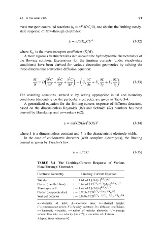
The resulting equations, arrived at by setting appropriate initial and boundary
conditions (depending on the particular electrode), are given in Table 3-4.
A generalized equation for the limiting-current response of different detectors,
based on the dimensionless Reynolds (Re) and Schmidt (Sc) numbers has been
derived by Hanekamp and co-workers (62):
b a
i nkFCD
Sc b
Re
3-34
l
where k is a dimensionless constant and b is the characteristic electrode width.
In the case of coulometric detectors (with complete electrolysis), the limiting
current is given by Faraday's law:
i nFCU
3-35
l
TABLE 3-4 The Limiting-Current Response of Various
Flow-Through Electrodes
Electrode Geometry Limiting Current Equation
Tubular i 1:61 nFC
DA=r 2=3 U 1=3
n
Planar (parallel ¯ow) i 0:68 nFCD 2=3 1=6
A=b 1=2 U 1=2
Thin-layer cell i 1:47 nFC
DA=b 2=3 U 1=3
n
Planar (perpendicular) i 0:903nFCD 2=3 1=6 3=4 1=2
A
u
n
a
A
Wall-jet detector i 0:898nFCD 2=3 5=12 1=2 3=8 U 3=4
a diameter of inlet; A electrode area; b channel height;
C concentration (mM); F Faraday constant; D diffusion coef®cient;
n kinematic viscosity; r radius of tubular electrode; U average
1
volume ¯ow rate; u velocity (cm s ); n number of electrons.
Adapted from reference 62.