
Page 36 - Analytical Electrochemistry 2d Ed - Jospeh Wang
P. 36
1-3 THE ELECTRICAL DOUBLE LAYER 21
where C H and C G represent that capacitance of the compact and diffuse layers,
respectively. The smaller of these capacitances determines the observed behavior. By
analogy with a parallel-plate (ideal) capacitor, C is given by
H
e
C
1-47
H
4pd
where d is the distance between the plates and e the dielectric constant (e 78 for
water at room temperature.) Accordingly, C increases with decreasing separation
H
between the electrode surface and the counterionic layer, as well as with increasing
dielectric constant of the intervening medium. The value of C is strongly affected
G
by the electrolyte concentration; the compact layer is largely independent of the
concentration. For example, at suf®ciently high electrolyte concentration, most of the
charge is con®ned near the Helmholz plane, and little is scattered diffusely into the
solution (i.e., the diffuse double layer becomes small). Under these conditions,
1=C 1=C ,1=C ' 1=C H or C ' C . In contrast, for dilute solutions, C is
H
H
G
G
very small (compared to C ) and C ' C .
G
H
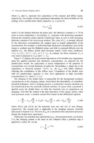
Figure 1-13 displays the experimental dependence of the double-layer capacitance
upon the applied potential and electrolyte concentration. As expected for the
parallel-plate model, the capacitance is nearly independent of the potential or
concentration over several hundreds of millivolts. Nevertheless, a sharp dip in the
capacitance is observed (around 0.5 V; i.e., the E pzc ) with dilute solutions,
re¯ecting the contribution of the diffuse layer. Comparison of the double layer
with the parallel-plate capacitor is thus most appropriate at high electrolyte
concentrations (i.e., when C ' C ).
H
The charging of the double layer is responsible for the background (residual)
current known as the charging current, which limits the detectability of controlled-
potential techniques. Such a charging process is nonfaradaic because electrons are
not transferred across the electrode±solution interface. It occurs when a potential is
applied across the double layer, or when the electrode area or capacitances are
changing. Note that the current is the time derivative of the charge. Hence, when
such processes occur, a residual current ¯ows based on the differential equation
dq dE dA dC dl
i C A C
E E pzc A
E E pzc
1-48
dl
dl
dt dt dt dt
where dE=dt and dA=dt are the potential scan rate and rate of area change,
respectively. The second term is applicable to the dropping mercury electrode
(discussed in Section 4-2). The term dC =dt is important when adsorption processes
dl
change the double-layer capacitance.
Alternately, for potential-step experiments (e.g., chronoamperometry, see Section
3-1), the charging current is the same as that obtained when a potential step is
applied to a series RC circuit:
E
i e t=RC dl
1-49
c
R
S