
Page 35 - Analytical Electrochemistry 2d Ed - Jospeh Wang
P. 35
20 FUNDAMENTAL CONCEPTS
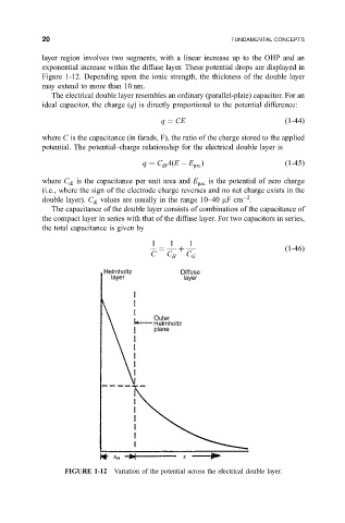
layer region involves two segments, with a linear increase up to the OHP and an
exponential increase within the diffuse layer. These potential drops are displayed in
Figure 1-12. Depending upon the ionic strength, the thickness of the double layer
may extend to more than 10nm.
The electrical double layer resembles an ordinary (parallel-plate) capacitor. For an
ideal capacitor, the charge (q) is directly proportional to the potential difference:
q CE
1-44
where C is the capacitance (in farads, F), the ratio of the charge stored to the applied
potential. The potential±charge relationship for the electrical double layer is
q C A
E E pzc
1-45
dl
where C is the capacitance per unit area and E is the potential of zero charge
dl pzc
(i.e., where the sign of the electrode charge reverses and no net charge exists in the
2
double layer). C values are usually in the range 10±40 mFcm .
dl
The capacitance of the double layer consists of combination of the capacitance of
the compact layer in series with that of the diffuse layer. For two capacitors in series,
the total capacitance is given by
1 1 1
1-46
C C C
H G
FIGURE 1-12 Variation of the potential across the electrical double layer.