
Page 201 - APPLIED PROCESS DESIGN FOR CHEMICAL AND PETROCHEMICAL PLANTS, Volume 1, 3rd Edition
P. 201
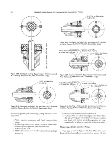
174                      Applied Process Design for Chemical and Petrochemical Plants
                                                                                                 2 N.P.T's  for  Circulating
                                                                                            /Lubrication   I


                                                                   Figure 3-26. Circulating lubrication. (By permission, H.  P.  Hummer
                                                                   and W. J. Ramsey, Bulletin SD 752, O&T3 Durametallic Corp.)


                                                                                          r- --- -- - -- 7-
                                    I
                                                                  or  By-pass from  Discharge


             Figure 3-24. Gland plate cooling. (By permission, H. P.  Hummer and   Figure 3-27. Flushing inside seal. (By permission, H. P.  Hummer and
             W.  J. Ramsey, Bulletin SD 752, O&T, Durametallic Corp.)
                                                                   W.  J. Ramsey, Bulletin SD 752, O&T, Durametallic Corp.)
                                            I  NIT, for  Dead-End                          I-------
                                        / Lubrication             Product Recirculat


             Figure 3-25. Dead-end lubrication. (By  permission,  H.  P.  Hummer   Figure 3-28. Flushing outside seal.  (By permission, H.  P.  Hummer
             and W.  J.  Ramsey. Bulletin SD 752, O&T,  Durametallic Corp.)   and W.  J. Ramsey, Bulletin SD 752, O&T, Durametallic Corp.)

             Generally speaking the centrifugal pump has these char-   6. Develops turbulent conditions in fluids
             acteristics:                                             7. Turbine type: (a) offers very high heads at low flows,
                                                                        (b) self-priming, (c) limited to very clean, non-abra-
                1. Wide  capacity,  pressure,  and  fluid  characteristics   sive fluids with limited physical properties,  (d) clear-
                  range                                                 ances can be problem on assembly and maintenance.
                2. Easily adapted to direct motor, V-belt or other drive
                3. Relatively small ground area requirements       Single-Stage (Single Impeller) Pumps
                4. Relatively low cost
                5. Difficult to obtain very low flows at moderate to high   This type of  pump  (Figures 3-1, 3-2, 3-3) is the work-
                  pressures                                        horse of the chemical and petrochemical industry. It also