
Page 199 - APPLIED PROCESS DESIGN FOR CHEMICAL AND PETROCHEMICAL PLANTS, Volume 1, 3rd Edition
P. 199
172 Applied Process Design for Chemical and Petrochemical Plants
The "single" mechanical seal is made of a rotating ele- used under various conditions in the wide variety of
ment fixed to the shaft (or shaft sleeve), and a stationary process fluids.
element fixed to the pump casing [ 161. The average unbalanced external seal is good for pres-
The "double" seal is for severe sealing problems where sures of about 30 psig, while the balanced design will han-
out-leakage to the environment cannot be tolerated and dle 150 psig. Special designs will handle much higher
must be controlled. (See Figures 3-31C and 3-31D.)
Depending upon the fluid's characteristics, the vent
Flush
between the double seals (Figures 3-31A and B) may be Gland connection
gasket
purged with process liquid, or a different liquid or oil, or t I / /
Gland
it may be connected to a seal pot and vent collection to Stuff in@-box Drive pi? I I , I I'rina
I
/
prevent leakage to the air/environment. There are tech- houska ', I I I I'
niques for testing for leakage of the inner seal by measur-
ing the vent space pressure through the seal liquid surge
port. This should be essentially atmospheric (depending
on the vent system backpressure). This allows detection
before the leakage breaks through the outer seal.
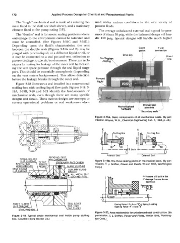
Figure 318 illustrates a seal installed in a conventional
stuffing box with cooling liquid flow path. Figures 3-18, 3-
19A, 3-19B, 3-20 and 3-21 identify the fundamentals of
mechanical seals, even though there are many specific
designs and details. These various designs are attempts to
correct operational problems or seal weaknesses when
i / Prirnaii,seal t
Mechanical-seal e,ements .'
I
hardware '.
"secondary seals"
Figure 3-19A. Basic components of all mechanical seals. (By per-
mission, Adams, W. H., Chemical Engineering Feb. 7, 1983, p. 48.)
c. e
Figure 3-198. The three sealing points in mechanical seals. (By per-
mission, T. J. Sniffen, Power and Fluids, Winter 1958, Worthington
Corp.)
P:Prauura of Liquid in Box
P': Average Presaura Across
-e.--- ----t--fi-
I
Closing Forcr : x Area "A" + Spring Loading
P
Opening Force : P' x Area "6"
Figure 3-20. Area relationship for unbalanced seal construction. (By
Figure 3-18. Typical single mechanical seal inside pump stuffing permission, T. J. Sniffen, Power and Fluids, Winter 1958, Worthing-
box. (Courtesy Borg-Warner Co.) ton Corp.)