
Page 202 - APPLIED PROCESS DESIGN FOR CHEMICAL AND PETROCHEMICAL PLANTS, Volume 1, 3rd Edition
P. 202
Pumping of Liquids d 75
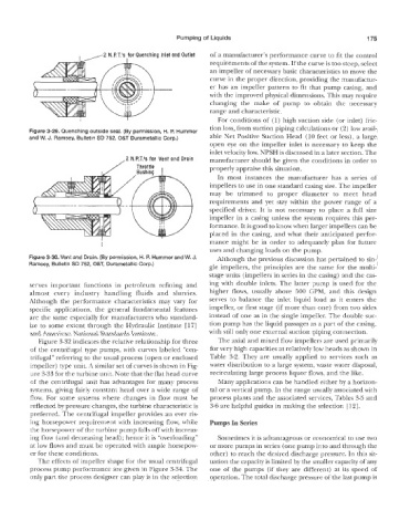
2 , , - N.F!T.’s fo~ Quenching Inlet and Outlet of a manufacturer’s performance curve to fit the control
requirements of the system. If the curve is too steep, select
an impeller of necessary basic characteristics to move the
curve in the proper direction, providing the manufactur-
er has an impeller pattern to fit that pump casing, and
with the improved physical dimensions. This may require
changing the make of pump to obtain the necessary
range and characteristic.
For conditions of (1) high suction side (or inlet) fric-
tion loss, from suction piping calculations or (2) low avail-
Figure 3-29. Quenching outside seal. (By permission, H. P. Hummer
amsey, Bulletin SD 752, Q&T Durametallic Corp.) able Net Positive Suction Head (BO feet or less), a large
open eye on the impeller inlet is necessary to keep the
inlet velocity low. NPSH is discussed in a later section. The
,2 M.P.T.ls for Vent and Drain manufacturer should be given the conditions in order to
Throttle properly appraise this situation.
I Bushing I
In most instances the manufacturer has a series of
impellers to use in one standard casing size. The impeller
may be trimmed to proper diameter to meet head
requirements and yet stay within the power range of a
specified driver. It is not necessary to place a full size
impeller in a casing unless the system requires this per-
formance. It is good to know when larger impellers can be
placed in the casing, and what their anticipated perfor-
mance might be in order to adequately plan for future
uses and changing loads on the pump.
Figure 3-30. Vent and Drain. (By permission, H. P. Hummer and W. J. Although the previous discussion has pertained to sin-
Ramsey, Bulletin SD 752, O&T, Durarnetallic Corp.)
gle impellers, the principles are the same for the multi-
stage units (impellers in series in the casing) and the cas-
serves important fuinctions in petroleum refining and ing with double inlets. The latter pump is used for the
almost every industry handling fluids and slurries. higher flows, usually above 500 GPM, and this design
Although the performance characteristics may vary for serves to balance the inlet liquid load as it enters the
specific applications. the general fundamental features impeller, or first stage (if more than one) from t~io sides
are the same especially for manufacturers who standard- instead of one as in the single impeller. The double suc-
ize to some extent tlirough the Hydraulic Institute [l’i] tion pump has the liquid passages as a part of the casing,
and American National Standards Institute. with still only one external suction piping connection.
Figure 3-32 indicates the relative relationship for three The axial and mixed flo~7 impellers are used primarily
of the centrifugal type pumps, with curves labeled “cen- for very high capacities at relatively low heads as shown in
trifugal” referring to the usual process (open or enclosed Table 3-2. They are usually applied to services such as
impeller) type unit. A similar set of curves is shown in Fig- water distribution to a large system, waste water disposal,
are 3-33 for the turbine unit. Note that the flat head curve recirculating large process liquor flows, and the like.
of the centrifugal unit has advantages for many process Many applications can be handled either by a horizon-
systems, giving fairly constant head over a wide range of tal or a vertical pump. In the range usually associated with
flow. For some systems where changes in flow must be process plants and the associated services, Tables 3-5 and
reflected by pressure changes, the turbine characteristic is 3-6 are helpful guides in making the selection [ 121.
preferred. The centrifugal impeller provides an ever ris-
ing horsepower requirement with increasing flow, while Pumps In Series
the horsepower of the turbine pump falls off with increas-
ing flow (and decreasing head) ; hence it is “overloading” Sometimes it is advantageous or economical to use two
at low Rows and must be operated with ample horsepow- or more pumps in series (one pump into and through the
er for these conditions. other) to reach the desired discharge pressure. In this sit-
The effects of impeller shape for the usual centrifugal uation the capacity is limited by the smaller capacity of any
process pump performance are given in Figure 3-34. The one of the pumps (if they are different) at its speed of
only part the process designer can ]play is in the selection operation. The total discharge pressure of the last pump is