
Page 197 - APPLIED PROCESS DESIGN FOR CHEMICAL AND PETROCHEMICAL PLANTS, Volume 1, 3rd Edition
P. 197
170 Applied Process Design for Chemical and Petrochemical Plants
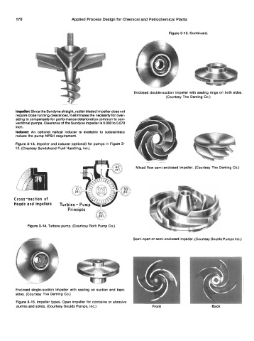
Figure 3-15. Continued.
Enclosed double-suction impeller with sealing rings on both sides.
(Courtesy The Deming Co.)
Irnpellec Since the Sundyne stralght, radlal-bladed Impeller does not
require close running clearances, It eliminates the necessity for over-
sizing to compensate for performance deterioration common to con-
ventional pumps. Clearance of the Sundyne Impeller Is 0.030 to 0.070
inch.
Inducer: An optlonal helical Inducer is available to substantially
reduce the pump NPSH requirement.
Figure 3-13. Impeller and inducer (optional) for pumps in Figure 3-
12. (Courtesy Sundstrand Fluid Handling, Inc.)
Mixed flow semi-enclosed impeller. (Courtesy The Deming Co.)
Cross-section of
Heads and Impellers
Principle -6
Figure 3-14. Turbine pump. (Courtesy Roth Pump Co.)
Semi-open or semi-enclosed impeller. (Courtesy Goulds Pumps Inc.)
Enclosed single-suction Impeller with sealing on suction and back
sides. (Courtesy The Deming Co.)
Figure 3-15. Impeller types. Open impeller for corrosive or abrasive
slurries and solids. (Courtesy Goulds Pumps, Inc.) Front Back