
Page 317 - Applied Process Design For Chemical And Petrochemical Plants Volume II
P. 317
306 Applied Process Design for Chemical and Petrochemical Plants
Thii design presentation is proprietary to Nutter Engi-
. 11-12 NUrTER RINGS neering and is definitely more accumte than applying the
. 0-2' PALL RINGS
1.50 1 Q--5.9' PALL RINGS Nutter RingTM to the generalized pressure drop correla-
tions (Figure 9-21B to -21F). Figures 9-21G and 9-211 do
0
cu
1 not apply because they are proprietary to another manu-
facturer. The procedures to follow supercede the equa-
tions in Nutter and Perry [99, 981, and are used by per-
mission of Nutter Engineering, a Harsco Corp.
1. Determine % useful capacity; Assume a column diam-
eter, or calculate using an existing column under
study. Usable capacity is defined as the maximum
loading condition where efficiency does not deterie
rate significantly from that achieved over a lower
range of loadings [99]. For the Nutter ring, the limit-
ing pressure drop for usable capacity is 1 in. of hot
2.00 C6/C7, 5 psia liquid for low pressure systems. Designs should not
FRI TDP, 5 mrn TUBES
exceed this value. This has been shown to hold for
A- X2 NUTTER RINGS f P, c647 system at 5 psia and for hydrocarbons at atmos
0-2" PALL RINGS
0-3.5" PALL RINGS pheric to 24 psia. (See Figures 9-31A and 9-31B) [98].
9% Useful capacity = (100) (CJ (FJC2) (9 - 39)
where C, - vapor rate =V, [&/(PI - ft/sec (9 - 40)
pv - vapor/gas phase density, lb/@
p1 - liquid phase density, lb/@
Vs = vapor superficial velocity, ft/sec
C, - wet pressure drop intercept coefficient
(FQI) (Fsize) (Fsystem) (9 - 41)
FQ~ - liquid rate factor for C2
FsiX - size factor for Cz
FVtem = physical properties factor for C2
F, - useful system capacity factor
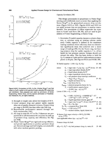
Figure 991C. Comparlson of P/Eo for No. 2 Nutter RingsTM and Pall (9 - 42)
rings in a C& system at 24 psia and 5 psia using the FRI tubed drip (0.533) ((PI - p~)/p~,)O.l~
pan distributor. Data prepared and used by permission of Nutter Limits: 0.728 e - F, < - 1.04
Engineering, Harsco Corp. and by special permission of Fractiona-
tion Research, Inc.; all rights resewed. FQJ - 0.428 - 0.0141 Q1 + 0.000326 Q' - 3.7
x QS + 1.47 x lo-* Q4 (9 - 43)
a liquid superficial velocity, gpm/ft2
8. Strength to weight ratio allows bed heights of 50 ft. F, - vapor rate, V, (pJ0.5, (ft/sec) (lb/ft3)o.5 (9 - 44)
9. Lower pressure drop and greater usable capacity XI + Xg (Qd (9 - 45)
Fsize
allow use of smaller diameter columns. Pressure drop XI, X2 - constants from Table 9-32
per stage is SO-SO% less than either size Pall ring.
10. Reproducible performance assured through uni- Fsystem - 1.130 (o/p1)0.'79 (9 - 46)
form randomness [ 1561. u - surface tension, liquid, dynes/cm
11. All rings in sizes No. 0.7 to No. 3 diameter are pre % System limit vapor velocity = 100 V,/[ (0.760)
portional on all dimensions for accuracy in scaleup WP, )0-4611 (9 - 47)
of pressure drop, capacity, and efficiency. See Fig- (not applicable when ((PI- &)/pv)Oe5 > 4.5
ure MK.
12. Plastic Nutter RingsTM are rigid and energy efficient, Pressure drop: dry bed
and permit applications to produce pressure drops
per theoretical stage and bed heights, not attainable dpd = C1 (FJ2 = dry bed pressure drop, in. water/ft (9 - 48)
with other random Darticle Dackinc.
"
I