
Page 362 - Applied Process Design For Chemical And Petrochemical Plants Volume II
P. 362
Packed Towers 351
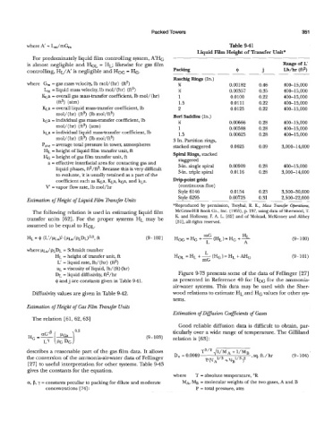
where A = L,/mG, Table 9-41
Liquid Film Height of Transfer Unit*
For predominately liquid film controlling system, A'HG
is almost negligible and HOL = HL; likewise for gas film Range of L'
controlling, HL/A' is negligible and HOG = HG. Packing 9 j Lb/h (ftz)
~- -. -. .-
Raschig Rings (In.)
where G,,, = gas mass velocity, Ib mol/(hr) (ft2) 36 0.00 182 0.46 400-15,000
L, = liquid mass velocity, lb mol/(hr) (ft2) !4 0.00357 0.35 400-15,000
Kc;a = overall gas mass-transfer coefficient, lb mol/(hr) 1 0.0100 0.22 400-15,000
(ft3) (am) 1.5 0.0111 0.22 400-15,000
KLa = overall liquid mass-transfer coefficient, Ib 2 0.0125 0.22 400-15,000
mol/(hr) (ft3) (lb mol/ft3) Berl Saddles (In.)
kGa = individual gas mass-transfer coefficient, lb M 0.00666 0.28 400-15,000
mol/(hr) (ft3) (am) 1 0.00588 0.28 400-15,000
kLa = individual liquid mass-transfer coefficient, lb 1.5 0.00625 0.28 400-15,000
mol/(hr) (ft3) (lb mol/ft3) 3 In. Partition rings,
Pa,, = average total pressure in tower, atmospheres stacked staggered 0.0623 0.09 3,000-14,000
HL = height of liquid film transfer unit, ft
HG = height of gas film transfer unit, ft Spiral Rings, stacked
staggered
a = effective interfacial area for contacting gas and 3-in. single spiral 0.00909 0.28 400-15,000
liquid phases, f$/ft3. Because this is very difficult 3-in. triple spiral 0.28 3,000-14,000
to evaluate, it is usually retained as a part of the 0.0116
coefficient such as &a, KLa, kGa, and kLa. Drippoiut grids
V = vapor flow rate, Ib mol/hr (continuous flue)
Style 6146 0.0154 0.23 3,500-30,000
Estimation of Height of Liquid Film Tranqer Units Style 6295 0.00725 0.31 2,~00-22,000
*Reproduced by permission, Treybal, R. E., Mass Tranqer Operations,
The following relation is used in estimating liquid film McGraw-Hill Book Co., Inc. (19.55), p. 237, using data of Sherwood, T.
transfer units [62]. For the proper systems HL may be K and Holloway, F. A. L. [62] and of Molsrad, McKinney and Abbey
[51], all rights reserved.
assumed to be equal to HOL.
mG
HL = 4 (L'/pLa$ (PLJPLDL)'.~, ft (9 - 102) HoG=HG+-(HL)=HG+- HL (9- 100)
L A
where ~IJPLDL = Schmidt number H~L=HL+-(HG)=HL+AHG
L
€3~ height of transfer unit, ft (9- 101)
=
L' = liquid rate, lb/ (hr) (ft2) mG
UL = viscosity of liquid, lb/ (ft) (hr)
DL = liquid diffusivity, ftn/hr Figure 9-73 presents some of the data of Fellinger [27]
9 and j are constants given in Table 941. as presented in Reference 40 for HOG for the ammonia-
air-water systems. This data may be used with the Sher-
Diffusivity values are given in Table 9-42. wood relations to estimate HL and HG values for other sys-
tems.
Estimation of Height of Gas Film Transfer Units
Estimation of Diffusion CoefJicients of Gases
The relation [61, 62, 631
Good reliable diffusion data is difficult to obtain, par-
ticularly over a wide range of temperature. The Gilliland
(9 - 103) relation is [63] :
describes a reasonable part of the gas film data. It allows
the conversion of the ammonia-air-water data of Fellinger
[27] to useful interpretation for other systems. Table 943
gives the constants for the equation.
where T = absolute temperature, "R
a, p, y = constants peculiar to packing for dilute and moderate MA, MB = molecular weights of the two gases, A and B
concentrations [ 741 : P = total pressure, atm