
Page 363 - Applied Process Design For Chemical And Petrochemical Plants Volume II
P. 363
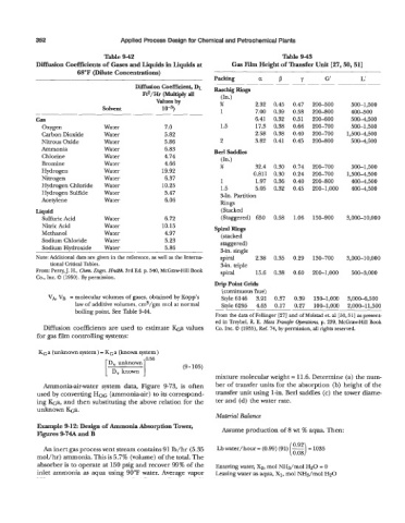
352                       Applied Process Design for Chemical and Petrochemical Plants

                                 Table 9-42                                            Table 9-43
            Diffusion Coefficients of Gases and Liquids in Liquids at   Gas Film Height of Transfer Unit [27,50,51]
                         68°F (Dilute Concentrations)
                                                                  Packing       a    P      Y       G'         L'
                                          Diffusion Coefficient, DL   RaschigRhlgs            ~                  ~
                                                                            ~
                                            Ftz/Hr  (Multiply  all   (In.)
                                                Values by           36         2.32   0.45   0.47
                                Solvent           10-5)             1          7.00   0.39   0.58   200-500   500-1,500
                                                           ~                                    200-800     400-500
            Gas                                                               6.41  0.32   0.51   200-600   5004,500
              Oxygen             Water             7.0              1.5        17.3  0.38   0.66   200-700   500-1,500
              Carbon Dioxide     Water             5.82                       2.58  0.38   0.40   200-700   1,5004,500
              Nitrous Oxide      Water             5.86             2         3.82  0.41   0.45   200-800   5004,500
              Ammonia            Water             6.83           Berl Saddles
              Chlorine           Water             4.74
                                                                    (In.)
              Bromine            Water             4.66             %          32.4  0.30   0.74   200-700   500-1,500
              Hydrogen           Water            19.92                       0.811  0.30   0.24   200-700   1,500-4,500
              Nitrogen           Water             6.37             1          1.97  0.36   0.40   200-800   4004,500
              Hydrogen Chloride   Water           10.25             1.5        5.05  0.32   0.45   200-1,000   4004,500
              Hydrogen Sulfide   Water             5.47             3-In. Partition
              Acetylene          Water             6.06             Rings
            Liquid                                                  (Stacked
              Sulfuric Acid      Water             6.72             (Staggered)  650   0.58   1.06   150-900   3,000-10,000
              Nitric Acid        Water            10.15           spiral Rings
              Methanol           Water             4.97             (stacked
              Sodium Chloride    Water             5.23             staggered)
              Sodium Hydroxide   Water             5.86             %in. single
            Note: Additional data are given in the reference, as well as the Interna-   spiral   2.38  0.35   0.29   130-700   3,000-10,000
                tional Critical Tables.                             3-in. triple
            From: Perry,  J. H., Cha. Engrs. Hndbk. 3rd Ed. p. 540, McGraw-Hill Book   spiral   15.6  0.38   0.60   200-1,000   500-3,000
            Co., Inc. 0 (1950). By permission.
                                                                  Drip Point Grids
                                                                    (continuous flue)
               VA, VB  = molecular volumes of gases, obtained by Kopp's   Style 6146   3.91  0.37   0.39   130-1,000   3,0004,500
                        law of additive volumes, cm3/gm mol at normal   Style 6295   4.65  0.17   0.27   100-1,000   2,000-11,500
                        boiling point. See Table 9-44.
                                                                  From the data of Fellinger [27] Fd of Molstad et. al [30,51] as present-
                                                                  ed in Treybel, R. E. Mass Transfer Opmutions, p. 239, McGraw-Hill Book
              Diffusion  coefficients are used  to  estimate &a  values   Co. Inc. 0 (1955), Ref. 74, by permission, all rights reserved.
            for gas film controlling systems:

             KGa (unknown system)  = KGa (known system)
                                 [  D,  known  ]  0.56   (9 - 105)
                                  D,  unknown
                                                                  mixture molecular weight = 11.6. Determine (a) the num-
              Ammonia-air-water system  data,  Figure  9-73,  is  often   ber of transfer units for the absorption  (b) height of the
            used by converting HOG (ammonia-air) to its correspond-   transfer unit using 1-in. Berl saddles (c) the tower diame-
            ing &a,  and then substituting the above relation for the   ter and (d) the water rate.
            unknown ka.
                                                                  Material Balance
            Example 9-12: Design of Ammonia Absorption Tower,       Assume production of 8 wt % aqua. Then:
            Figures 9-74A and B
                                                                                         ( Z)
              An inert gas process vent stream contains 91 lb/hr  (5.35   Lb water/ hour  = (0.99) (91)  - = 1035
            mol/hr)  ammonia. This is 5.7% (volume) of the total. The
            absorber is to operate at 150 psig and recover 99% of the   Entering water, Xz, mol NHs/mol H20 = 0
            inlet ammonia  as aqua using 90°F water. Average vapor   Leaving water as aqua, XI, mol NHg/mol H20