
Page 105 - Artificial Intelligence for Computational Modeling of the Heart
P. 105
Chapter 2 Implementation of a patient-specific cardiac model 75
fs plane, i.e. along the f 0 direction, is described with the following
deformation gradient (Fig. 2.24):
⎡ ⎤
1 γ 0
F = 0 1 0 ⎦ (2.28)
⎣
0 0 1
resulting in the following
1 γ 0
⎡ ⎤
2
C = γ γ + 1 0 , f = f 0 , s = γ f 0 + s 0 , n = n 0 . (2.29)
⎣
⎦
0 0 1
2 2
The invariants then write I 1 = 3 + γ , I 4 s = 1 + γ and I 4 f = I 4 n =
1, and the shear stress becomes:
2
4
3
2
T = aγ exp(bγ ) + 2a s γ exp(b s γ ) + a fs γ exp(b fs γ ) (2.30)
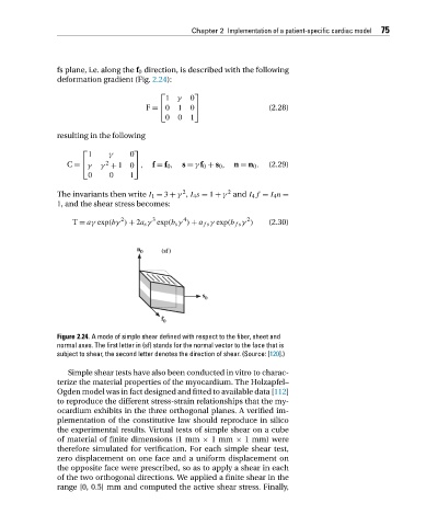
Figure 2.24. A mode of simple shear defined with respect to the fiber, sheet and
normal axes. The first letter in (sf) stands for the normal vector to the face that is
subject to shear, the second letter denotes the direction of shear. (Source: [120].)
Simple shear tests have also been conducted in vitro to charac-
terize the material properties of the myocardium. The Holzapfel–
Ogden model was in fact designed and fitted to available data [112]
to reproduce the different stress-strain relationships that the my-
ocardium exhibits in the three orthogonal planes. A verified im-
plementation of the constitutive law should reproduce in silico
the experimental results. Virtual tests of simple shear on a cube
of material of finite dimensions (1 mm × 1mm × 1 mm) were
therefore simulated for verification. For each simple shear test,
zero displacement on one face and a uniform displacement on
the opposite face were prescribed, so as to apply a shear in each
of the two orthogonal directions. We applied a finite shear in the
range [0, 0.5] mm and computed the active shear stress. Finally,