
Page 76 - Artificial Intelligence for Computational Modeling of the Heart
P. 76
46 Chapter 2 Implementation of a patient-specific cardiac model
Figure 2.3. From left to right: final geometrical models extracted from computed
tomography (CT), magnetic resonance image (MRI) or ultrasound data.
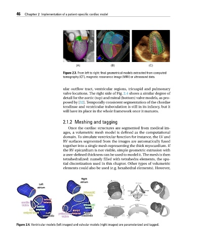
ular outflow tract, ventricular regions, tricuspid and pulmonary
valve locations. The right side of Fig. 2.4 shows a similar degree of
detail for the aortic (top) and mitral (bottom) valve models, as pro-
posed by [32]. Temporally consistent segmentation of the chordae
tendinae and ventricular trabeculation is still in its infancy, but it
will have its place in the whole framework once it matures.
2.1.2 Meshing and tagging
Once the cardiac structures are segmented from medical im-
ages, a volumetric mesh model is defined as the computational
domain. To simulate ventricular function for instance, the LV and
RV surfaces segmented from the images are automatically fused
together into a single mesh representing the thick myocardium. If
the RV epicardium is not visible, simple geometric extrusion with
a user-defined thickness can be used to model it. The mesh is then
tetrahedralized: namely filled with tetrahedra elements, the spa-
tial discretization used in this chapter. Other types of volumetric
elements could also be used (e.g. hexahedral elements). However,
Figure 2.4. Ventricular models (left images) and valvular models (right images) are parameterized and tagged.