
Page 79 - Artificial Intelligence for Computational Modeling of the Heart
P. 79
Chapter 2 Implementation of a patient-specific cardiac model 49
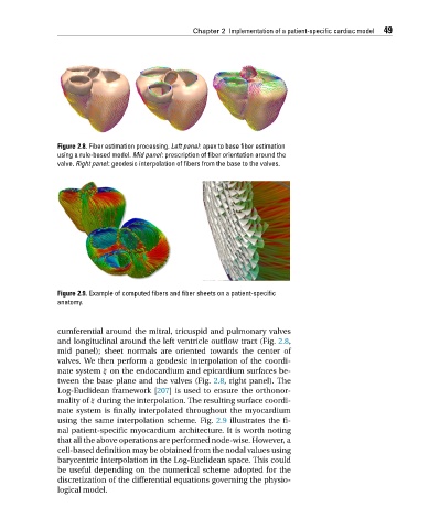
Figure 2.8. Fiber estimation processing. Left panel: apex to base fiber estimation
using a rule-based model. Mid panel: prescription of fiber orientation around the
valve. Right panel: geodesic interpolation of fibers from the base to the valves.
Figure 2.9. Example of computed fibers and fiber sheets on a patient-specific
anatomy.
cumferential around the mitral, tricuspid and pulmonary valves
and longitudinal around the left ventricle outflow tract (Fig. 2.8,
mid panel); sheet normals are oriented towards the center of
valves. We then perform a geodesic interpolation of the coordi-
nate system ξ on the endocardium and epicardium surfaces be-
tween the base plane and the valves (Fig. 2.8, right panel). The
Log-Euclidean framework [207] is used to ensure the orthonor-
mality of ξ during the interpolation. The resulting surface coordi-
nate system is finally interpolated throughout the myocardium
using the same interpolation scheme. Fig. 2.9 illustrates the fi-
nal patient-specific myocardium architecture. It is worth noting
that all the above operations are performed node-wise. However, a
cell-based definition may be obtained from the nodal values using
barycentric interpolation in the Log-Euclidean space. This could
be useful depending on the numerical scheme adopted for the
discretization of the differential equations governing the physio-
logical model.