
Page 78 - Artificial Intelligence for Computational Modeling of the Heart
P. 78
48 Chapter 2 Implementation of a patient-specific cardiac model
2.1.3 Computational model of the cardiac fiber
architecture
The implementation described in this chapter relies on a
rule-based model of myocardium architecture derived from ex-
vivo studies [49,55,56], following a similar strategy as in [45,
57]. The model, which covers fiber orientation and fiber sheets,
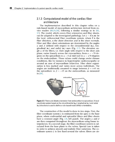
can be adapted to the investigated pathology. Let ξ = (f,s,n) be
the local, orthonormal fiber coordinate system, where f is the
fiber direction, s the sheet direction and n the sheet normals.
Fiber and fiber sheet orientations are determined by the angles
α and β defined with respect to the circumferential (e 0 ), lon-
gitudinal (e 1 ) and radial (e 2 )axes(Fig. 2.7). The elevation an-
gle α of the fibers, i.e. their angle with respect to the short axis
plane, varies linearly across the myocardium, from α =−70 de-
grees on the epicardium to α = 0 at mid-wall to α =+70 degrees
on the endocardium. These values could change under disease
conditions, like for instance in hypertrophic cardiomyopathy or
around an area of myocardium infarction. Fiber sheet organi-
zation is less marked and varies more across individuals. The
angles are traditionally assumed to range between β =+45 on
the epicardium to β =−45 on the endocardium, as measured
in [56].
Figure 2.7. Fibers and sheets orientation from endocardium to epicardium. A local
coordinate system based on the circumferential (e 0 ), longitudinal (e 1 ) and radial
(e 2 ) directions is used to define a rule-based model of fiber orientations.
The construction of the model is done in two steps. First, the
fiber coordinate system ξ is estimated from the apex to the base
plane, where endocardial and epicardial fibers and fiber sheets
have a constant angle (Fig. 2.8, left panel). The angles α and β
are then computed throughout the myocardium using linear in-
terpolation. In a second stage, the fiber coordinate system is cal-
culated from the base plane to the valves. Special care is taken
in order to achieve smooth and realistic fiber variations. The co-
ordinate system ξ is first fixed around the valves: fibers are cir-