
Page 340 - Automotive Engineering Powertrain Chassis System and Vehicle Body
P. 340
Tyre characteristics and vehicle handling and stability C HAPTER 11.1
As indicated in the figure, the complex root is char- which expression may be readily obtained with the aid of
acterised by the natural frequency u o of the undamped Eqs.(11.1.46) and (11.1.47).
system (D ¼ 0), the damping ratio z and the resulting The parameter influence has been indicated in the
actual natural frequency u n . Expressions for these figure. The results correspond qualitatively well with the
quantities in terms of the model parameters are rather 90% response times found in vehicle model simulation
complex. However, if we take into account that in studies. A remarkable result is that for an understeered
normal cases jsj l and q z k z ½ l we may simplify automobile the response time is smaller than for an
these expressions and find the following useful formulae:
oversteered car.
The natural frequency of the undamped system:
Forced linear vibrations
2
K C h 2
2
u ¼ z , 1 þ V (11.1.70) The conversion of the equations of motion (11.1.46)
o
M mV gl
into the standard state space representation is useful
The damping ratio: when the linear system properties are the subject of in-
vestigation. The system at hand is of the second order
D 1 and hence possesses two state variables for which we
z ¼ z r ffiffiffiffiffiffiffiffiffiffiffiffiffiffiffiffiffiffiffi (11.1.71)
2Mu o h 2 choose: v and r. The system is subjected to a single input
1 þ V
gl signal: the steer angle d. Various variables may be of in-
terest to analyse the vehicle’s response to steering input
The natural frequency: oscillations. The following quantities are selected to il-
lustrate the method and to study the dynamic behaviour
2 of the vehicle: the lateral acceleration a y of the centre of
2 2 2 C h
u ¼ u ð1 z Þz (11.1.72) gravity of the vehicle, the yaw rate r and the vehicle slip
o
n
m gl
angle b defined at the centre of gravity. In matrix nota-
tion, the equation becomes:
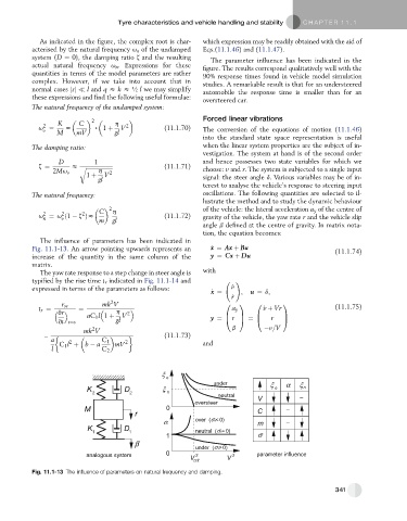
The influence of parameters has been indicated in
Fig. 11.1-13. An arrow pointing upwards represents an _ x ¼ Ax þ Bu (11.1.74)
increase of the quantity in the same column of the y ¼ Cx þ Du
matrix.
The yaw rate response to a step change in steer angle is with
typified by the rise time t r indicated in Fig. 11.1-14 and !
expressed in terms of the parameters as follows: _ v
_ x ¼ ; u ¼ d;
_ r
2
r ss mk V 0 1 0 1 (11.1.75)
t r ¼ ¼ a y _ v þ Vr
vr h 2
B
B
C
aC 1 l 1 þ V y ¼ @ r A ¼ @ r C
A
vt t¼0 gl
2
mk V b v=V
¼ (11.1.73)
a C 1
2
C 1 l þ b a mV 2 and
l C 2
Fig. 11.1-13 The influence of parameters on natural frequency and damping.
341