
Page 638 - Automotive Engineering Powertrain Chassis System and Vehicle Body
P. 638
CHAP TER 1 8. 2 Materials for consideration and use in automotive body structures
In 1971, 10 research had commenced on a more
Idealized roughness structures controlled system of surface preparation using electro-
for
discharge texturing (EDT), the surface being eroded as in
EDT machining by discharge of electrical energy through
a di-electric, the work roll being one of the electrodes (Fig.
18.2-9). As well as a more repeatable process the peak
formability glossiness of count can be double that achieved with equivalent shot
friction/abrasion painted sheet blasted finishes.
In 1982, more deterministic or specific roll surface
patterns were developed beginning with Lasertex which,
Description of roughness by as the name suggested, was produced by subjecting the
work roll surface to intermittent exposure employing
a mechanical chopper to cut the laser beam (Fig. 18.2-10).
R a value, skewness vertical R a value
average wavelength horizontal peak count This created a regular array of circular channels pro-
viding lubrication while maintaining a central core to
resist local deformation/wear. While this was excellent
for oil retention for deep drawn parts, the periodicity of
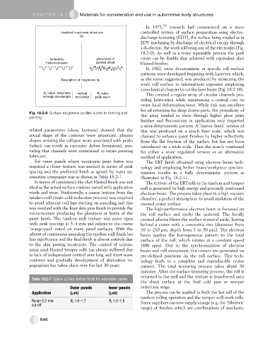
Fig. 18.2-8 Surface roughness profiles suited to forming and this array tended to show through higher gloss paint
painting.
finishes and fluctuations in application only imparted
a semi-deterministic pattern. A ‘mirror finish’ version of
related parameters (skew, kurtosis) showed that the this was produced on a much finer scale, which was
actual shape of the contours were important, plateau claimed to enhance paint finishes by higher reflectivity
shapes resisting the collapse more associated with peaks from the flat fraction of the surface but has not been
(which can result in excessive debris formation), pro- introduced on a wide scale. Thus the search continued
viding that channels were maintained to retain pressing for either a more regulated version or an alternative
lubricant. method of application.
For outer panels where maximum paint lustre was The EBT finish obtained using electron beam tech-
required a closer texture was needed in terms of peak nology and employing better beam/workpiece synchro-
spacing and the preferred finish as agreed by many au- nization results in a fully deterministic pattern as
tomotive companies was as shown in Table 18.2-7. illustrated in Fig. 18.2-11.
In terms of consistency the shot blasted finish was not The texture of the ERTrolls in the tandem and temper
ideal as the actual surface contour varied with application mill is generated by high energy and precisely positioned
mode and wear. Traditionally, a coarse texture from the electron beam. The process takes place in a high vacuum
tandem mill (main cold-reduction process) was required chamber, a perfect atmosphere to avoid oxidation of the
to avoid adjacent coil laps sticking on annealing and this created crater surface.
was overlaid with the finer skin pass finish to provide the Thehigh-performanceelectronbeamisfocussedon
micro-texture producing the glossiness or lustre of the the roll surface and melts the material. The locally
paint finish. The tandem mill texture was more open created plasma blows the molten material aside, leaving
with peak spacings at 3–4 mm and relates to the coarse behind a crater with a concentric rim (diameter from
‘orange-peel’ noted on many panel surfaces. With the 50 to 250 mm, depth from5to30 mm). The electron
advent of continuous annealing the tandem mill finish has beam applies the homogeneous pattern to the total
less significance and the final finish is almost entirely due surface of the roll, which rotates at a constant speed
to the skin passing treatment. The control of texture (600 rpm). Due to the synchronization of electron
using sand blasted temper rolls has always suffered due beam and roll movement, the craters are generated on
to lack of independent control over long and short wave pre-defined positions on the roll surface. This tech-
contours and gradually development of alternative to- nology leads to a complete and reproducible crater
pographies has taken place over the last 30 years. pattern. The total texturing process takes about 30
minutes. After the surface texturing process, the roll is
returned to the mill and the texture is transferred onto
Table 18.2-7 Typical surface texture finish for automotive panels
thesheet surfaceat thefinal cold pass or temper
Outer panels Inner panels reduction stage.
Application (mm) (mm) The process can be applied to both the last roll of the
tandem rolling operation and the temper mill work rolls.
Range 2.5 mm R a 1.0–1.7 R a 1.0–1.8 Some suppliers can now supply a range (e.g. the ‘Sibertex’
cut-off
range) of finishes which are combinations of stochastic
646