
Page 635 - Automotive Engineering Powertrain Chassis System and Vehicle Body
P. 635
Materials for consideration and use in automotive body structures C HAPTER 18.2
shown in Fig. 18.2-2(b)) limits the development of
Liquid steel favourable crystallographic textures and grain size, and as
a consequence ‘r’ values are lower and drawability is im-
Casting roll
paired. Yieldstresstends to be higher as itisrelated to grain
5
size by the Petch equation shown below,
s LYS ¼ s i þ k y d 1=2
where s i is the stress required to move free dislocations
2d is the grain diameter
k y is the effect of dislocation locking by impurity
atoms
Principle of twin-roll thin strip casting.
Relative properties for each type are shown in Table
Fig. 18.2-5 Principle of direct process of casting thin strip from
molten steel. 18.2-6.
However, as stated, through tool and press adjustment
options and duplex/multiphase structured steels can be and possibly the use of an enhanced lubricity mill oil,
produced more readily. similar performance can generally be achieved for the
Details of the differences between CAPL and BA same part.
processing are shown in Table 18.2-5.
Although requiring lower investment, the batch 18.2.2.2.1.5 Skin passing – effect on yield stress/
annealing processes commonly require 2–3 days for the yield point elongation
more formable grades of steel as opposed to 10 minutes Unless IF technology is used during the steelmaking
for the CAPL treatment, but even with the hydrogen process, the presence of carbon and nitrogen interstitial
atmosphere utilized by the Ebner process, which pro- atoms can lead to strain ageing on subsequent forming of
vides a higher heat transfer efficiency, the uniformity of the steel strip leading to the formation of stretcher-strain
properties is still a problem. marks on the surface, accompanied by a well-defined
The lower processing time, while providing a vastly yield point. This phenomenon is related to the pinning of
6
increased throughput via CAPL (Corus furnace section residual dislocations by the interstitial atoms and,
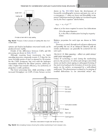
Furnace
Inner cover
Convector
Combustion chamber
Burner
Sand seal
Centrifuged fan
Schematic cross section through a bell annealing furnace.
Fig. 18.2-6 Bell annealing furnace showing the vertical positioning of cold reduced coils.
643