
Page 332 - Autonomous Mobile Robots
P. 332
320 Autonomous Mobile Robots
20
Leading
15
l=1 m
10 l=2.5 m
l=4 m
Steering angle (°) – 5
5
l=5.5 m
0
– 10
– 15
– 20
0 10 20 30 40 50
Time (sec)
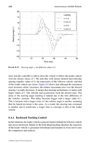
FIGURE 8.12 Steering angle γ for different values of l.
show that the controller is able to drive the vehicle to follow the leader vehicle
with the chosen values of l. We note that with shorter desired intervehicular
spacing (smaller values of l), the trajectories of the follower vehicle, and that
of the leader vehicle are closer. Figure 8.9 shows that although the maximum
error increases when l increases, the relative maximum error over the desired
spacing l actually decreases. It means that tracking performance is better with
larger values of l. The velocity and acceleration track the desired ones. The
delay in the steering angle tracking is natural due to the time difference of
the vehicles’ motions. This delay becomes bigger with a larger value of l.
This is because with a larger value of l the relative angle is smaller, assuming
that the lateral deviation is the same. As a result, the steering rate command
is smaller, and it would take a longer time to converge to that of the leader
vehicle.
8.4.2 Backward Tracking Control
In this situation, the leader vehicle is placed l meters behind the follower vehicle
and moves backward. Similar to the look-ahead tracking situation, the trajectory
of the leader vehicle is generated beforehand and repeated in every test to ease
the comparison and analysis.
© 2006 by Taylor & Francis Group, LLC
FRANKL: “dk6033_c008” — 2006/3/31 — 16:43 — page 320 — #26