
Page 239 - Battery Reference Book
P. 239
Nickel-cadmium secondary batteries 19/5
I Microporous separator I 0
I t -
I
I
I- Avaiiable-' I I , ,
I I capacity i 1 i k i i 0, production
li ! Charqing
..
reserve
$ i p =constant
t --------
a t
I
>
1
Normal ' Overcharge lu
charge
t-
Figure 19.2 Schematic diagram of the charging process in
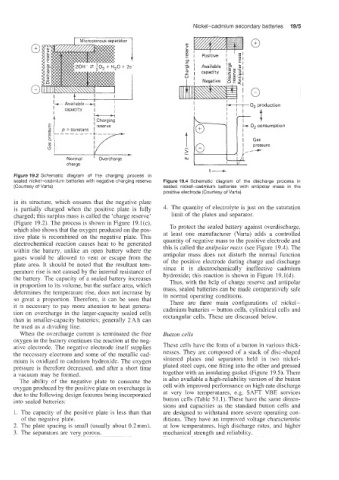
sealed nickel-cadmium batteries with negative charging reserve Figure 19.4 Schematic diagram of the discharge process in
(Courtesy of Varta) sealed nickel-cadmium batteries with antipolar mass in the
positive electrode (Courtesy of Varta)
in its structure, which ensures that the negative plate
is partially charged when the positive plate is fully 4. The quantity of electrolyte is just on the saturation
charged; this surplus mass is called the 'charge reserve' limit of the plates and separator.
(Figure 19.2). The process is shown in Figure 19.1(c),
which also shows that the oxygen produced on the pos- To protect the sealed battery against overdischarge,
itive plate is recombined on the negative plate. This at least one manufacturer (Varta) adds a controlled
electrochemical reaction causes heat to be generated quantity of negative mass to the positive electrode and
this is called the antipolar mass (see Figure 19.4). The
within the battery, unlike an open battery where the
gases would be allowed to vent or escape from the antipolar mass does not disturb the normal function
plate area. It should be noted that the resultant tem- of the positive electrode during charge and discharge
since it is electrochemically ineffective cadmium
perature rise is not caused by the internal resistance of hydroxide; this reaction is shown in Figure 19.1(d).
the battery. Tne capacity of a sealed battery increases Thus, with the help of charge reserve and antipolar
in proportion to its volume, but the surface area, which
determines the temperature rise, does not increase by mass, sealed batteries can be made comparatively safe
so great a proportion. Therefore, it can be seen that in normal operating conditions.
There are three main configurations of nickel-
it is necessary to pay more attention to heat genera- cadmium batteries - button cells. cylindrical cells and
tion on overchaLrge in the larger-capacity sealed cells rectangular cells. These are discussed below.
than in smaller-capacity batteries; generally 2 Ah can
be used as a dividing line.
When the ov'ercharge current is terminated the free Button cells
oxygen in the battery continues the reaction at the neg-
ative electrode. The negative electrode itself supplies These cells have the form of a button in various thick-
the necessary electrons and some of the metaIlic cad- nesses. They are composed of a stack of disc-shaped
mium is oxidized to cadmium hydroxide. The oxygen sintered plates and separators held in two nickel-
pressure is then-fore decreased, and after a short time plated steel cups, one fitting into the other and pressed
a vacuum may be formed. together with an insulating gasket (Figure 19.5). There
The ability of the negative plate to consume the is also available a high-reliability version of the button
oxygen produced by the positive plate on overcharge is cell with improved performance on high-rate discharge
due to the following design features being incorporated at very low temperatures, e.g. SAFT VBE services
into sealed batteries: button cells (Table 51.1). These have the same dimen-
sions and capacities as the standard button cells and
I. The capacity of the positive plate is less than that are designed to withstand more severe operating con-
of the negative plate. ditions. They have an improved voltage characteristic
2. The plate spacing is small (usually about 0.2mm). at low temperatures, high discharge rates, and higher
3. The separators are very porous. mechanical strength and reliability.