
Page 242 - Battery Reference Book
P. 242
19/8 Nickel batteries
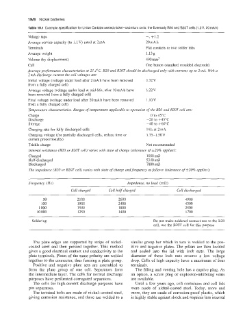
Table 19.1 Example specification for Union Carbide sealed nickel-cadmium cells: the Eveready 620 and B20T cells (1.2V, 20mAh)
~~
Voltage taps -, +1.2
Average service capacity (to 1.1 V) rated at 2 mA 20 mA h
Terminals Flat contacts or two solder tabs
Average weight 1.13g
Volume (by displacement) 490 mm3
Cell One button (standard moulded electrode)
Average performance characteristics at 2I.I"C. B20 and B20T should be discharged only with currents up to 2 mA. With a
2 mA discharge current the cell voltages are:
Initial voltage (voltage under load after 2 mA h have been removed 1.32V
from a fully charged cell)
Average voltage (voltage under load at mid-life, after l0mAh have 1.22 v
been removed from a fully charged cell)
Final voltage (voltage under load after 20 mA h have been removed l.10V
from a fully charged cell)
Temperature characteristics. Ranges of temperature applicable to operation of the B20 and B20T cell are:
Charge 0 to 45°C
Discharge -20 to +45T
Storage -40 to +60"C
Charging rate for fully discharged cells 14h at 2mA
Charging voltage (for partially discharged cells, reduce time or 1.35-lS0V
current proportionally)
Trickle charge Not recommended
Internal resistance (B20 or B20T cell) varies with state of charge (tolerance of f20% applies):
Charged 1000mfi
Half-discharged 5340 ma
Discharged 7800 ma
The impedance (B20 or B20T cell) varies with state of charge and frequency asfollows (tolerance of 520% applies):
Frequency (Hz) Impedance, no load (ma)
Cell charged Cell half charged Cell discharged
50 2100 2600 4900
100 1900 2400 4300
1 000 1500 1800 2500
10 000 1250 1450 1700
Soldering Do not make soldered connections to the B20
cell, use the B20T cell for this purpose
The plate edges are supported by strips of nickel- similar group bar which in turn is welded to the pos-
coated steel and then pressed together. This method itive and negative plates. The pillars are then located
gives a good electrical contact and conductivity to the and sealed into the lid with lock nuts. The large
plate terminals. Plates of the same polarity are welded diameter of these lock nuts ensures a low voltage
together to the connector, thus forming a plate group. drop. Cells of high capacity have a maximum of four
Positive and negative plate sets are assembled to terminals.
form the plate group of one cell. Separators form The filling and venting hole has a captive plug. As
the intermediate layer. The cells for normal discharge an option, a screw plug or explosion-inhibiting vents
purposes have perforated corrugated separators. are available.
The cells for high-current discharge purposes have Until a few years ago, cell containers and cell lids
pin separators. were made of nickel-coated steel. Today, more and
The terminal bolts are made of nickel-coated steel, more, they are made of corrosion-proof plastic, which
giving corrosion resistance, and these are welded to a is highly stable against shock and requires less internal