
Page 247 - Battery Reference Book
P. 247
Nickel-cadmium secondary batteries 19/13
metal-to-gas couple has resulted in the development Positive
of certain interesting and very successful internal cell electrode Gas smcer
design innovations, and this new technology could eas-
ily be applied to the sealed nickel-cadmium system.
By incorporating the gas recombination design pro-
visions of the nickel-hydrogen cell, the requirement
for a high porosity separator material in the sealed
nickel-cadmium cell is eliminated. High electrolyte
absorption and retention, and non-temperature and
non-time (cycle life) degradable inorganic separator
materials such as potassium titanate or asbestos may Teflon film
the hydrogen gas overvoltage potential of the negative -
be used. This same gas recombination also renders the
sealed nickel-cadmium system less sensitive to elec-
trolyte level increases of up to 50%, eliminating the
need to operate the cell in a virtually starved elec-
trolyte condition. Finally, by incorporating a small
section of the nickel-hydrogen gas electrode mater-
ial in unique electncal contact with the cell positive
terminal, a hydrogen gas recombination mechanism
(during charge and overcharge) is introduced. If, dur-
ing operation, the cell is stressed to the point at which
(cadmium) ellectrode is achieved, the evolved gas is Negative electrode
rapidly recombined at a low equilibrium pressure and
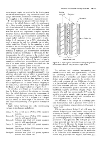
one of the more serious problems associated with the Figure 19.13 ‘Split negative’ electrode stack design: Eagle Picher
sealed nickel-cadmium cell (Courtesy of Eagle Picher)
sealed nickel-cadmium system is reduced.
The modified Eagle Picher nickel-cadmium cell
incorporates Ihe ‘split negative’ design in which a sin- The stainless steel container, incorporating two
gle negative or cadmium electrode is replaced by two ceramic-to-metal seals, was approximately 114.3 mm
cadmium electrodes each of which is approximately tall (excluding terminals) by 76.2 mm wide, by
one-half the thickness of the original. The two back- 22.9mm thick. To simulate a thin negative electrode
to-back negative electrodes are then separated by a gas design using available materials, the positive elec-
spacer component to facilitate gas access, as in the trodes used consisted of two 0.0064mm electrodes
nickel-hydrogen cell. To further enhame oxygen gas in a back-to-back configuration offering in effect a
recombination, a thin film of Teflon may be applied to 0.0127 mm electrode (positive). Each test cell incor-
the back of each negative electrode (Figure 19.13) porated five 0.0127 mm positive electrodes and ten
TQ introduce a hydrogen gas recombination ability 0.0064mm negative electrodes (Figure 19.12). The
into the design, a section of the catalytic gas electrode capacity of a cell was approximately 20Ah and the
from the nickel-hydrogen system is incorporated. A negative-to-positive capacity ratio was approximately
strip of this material, approximately the same width as 1.3:l. All cells were activated with electrolyte to a
the narrow edge of the cell, is wrapped in a U-shaped level of approximately 3.5 cm3/A h.
fashion around the entire edge of the electrode stack The influence of cell design on overcharge pres-
and connected electrically to the positive terminal of sure characteristics, that is, potential improvement in
the cell. oxygen recombination characteristics. is illustrated in
Eagle Picher fabricated test cells incorporating
various design features as follows: Figure 19.14.
With the exception of design D, all cells using the
Design A: Non-woven nylon (Pellon 2505) separator asbestos designs appear to recombine oxygen gas sat-
material. isfactorily at this rate. The high charge voltage associ-
Design €3: Non-woven nylon (Pellon 2505) separator ated with design D may have resulted in the hydrogen
material with gas electrode. gas overvoltage potential being exceeded and hence the
Design C: Asbestos mat (fuel cell grade) separator generation of high pressure. The hydrogen gas over-
material with gas electrode. voltage potential may have also been exceeded with
Design D: Asbestos mat (fuel cell grade) separator design C but, in this case, the design incorporated a
material. gas electrode which facilitated hydrogen gas recomb-
Design E: Non-woven (Pellon 2505) separator mater- ination. The relatively lower charge voltage associated
ial with Teflon film. with design F may have resulted from the application
Design F: Asbestos mat (fuel cell grade) separator of the Teflon film which enhanced oxygen gas recomb-
material with Teflon film. ination and maintained the negative electrodes at a