
Page 252 - Battery Reference Book
P. 252
19/18 Nickel batteries
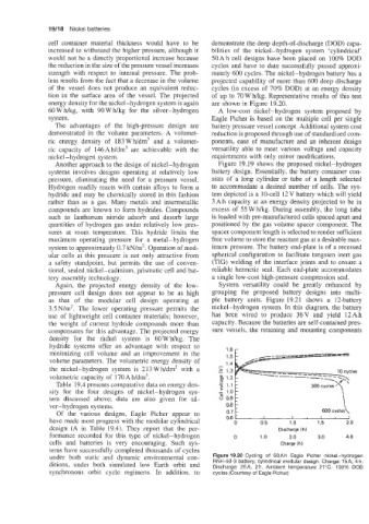
cell container material thickness would have to be demonstrate the deep depth-of-discharge (DOD) capa-
increased to withstand the higher pressure, although it bilities of the nickel-hydrogen system ‘cylindrical’
would not be a directly proportional increase because 50 Ah cell designs have been placed on 100% DOD
the reduction in the size of the pressure vessel increases cycles and have to date successfully passed approxi-
strength with respect to internal pressure. The prob- mately 600 cycles. The nickel-hydrogen battery has a
lem results from the fact that a decrease in the volume projected capability of more than 600 deep discharge
of the vessel does not produce an equivalent reduc- cycles (in excess of 70% DOD) at an energy density
tion in the surface area of the vessel. The projected of up to 70 W hkg. Representative results of this test
energy density for the nickel-hydrogen system is again are shown in Figure 19.20.
60 W Wkg, with 90 W Wkg for the silver-hydrogen A low-cost nickel-hydrogen system proposed by
system. Eagle Picher is based on the multiple cell per single
The advantages of the high-pressure design are battery pressure vessel concept. Additional system cost
demonstrated in the volume parameters. A volumet- reduction is proposed through use of standardized com-
ric energy density of 183 Wh/dm3 and a volumet- ponents, ease of manufacture and an inherent design
ric capacity of 146Ah/dm3 are achievable with the versatility able to meet various voltage and capacity
nickel-hydrogen system. requirements with only minor modifications.
Another approach to the design of nickel-hydrogen Figure 19.19 shows the proposed nickel-hydrogen
systems involves designs operating at relatively low battery design. Essentially, the battery container con-
pressure, eliminating the need for a pressure vessel. sists of a long cylinder or tube of a length selected
Hydrogen readily reacts with certain alloys to form a to accommodate a desired number of cells. The sys-
hydride and may be chemically stored in this fashion tem depicted is a 10-cell 12 V battery which will yield
rather than as a gas. Many metals and intermetallic 3 Ah capacity at an energy density projected to be in
compounds are known to form hydrides. Compounds excess of 55 W hkg. During assembly, the long tube
such as lanthanum nitride adsorb and desorb large is loaded with pre-manufactured cells spaced apart and
quantities of hydrogen gas under relatively low pres- positioned by the gas volume spacer component. The
sures at room temperature. This hydride limits the spacer component length is selected to render sufficient
maximum operating pressure for a metal-hydrogen free volume to store the reactant gas at a desirable max-
system to approximately 0.7 kN/m2. Operation of mod- imum pressure. The battery end-plate is of a recessed
ular cells at this pressure is not only attractive from spherical configuration to facilitate tungsten inert gas
a safety standpoint, but permits the use of conven- (TIG) welding of the interface joints and to ensure a
tional, sealed nickel-cadmium, prismatic cell and bat- reliable hermetic seal. Each end-plate accommodates
tery assembly technology. a single low-cost high-pressure compression seal.
Again, the projected energy density of the low- System versatility could be greatly enhanced by
pressure cell design does not appear to be as high grouping the proposed battery designs into multi-
as that of the modular cell design operating at ple battery units. Figure 19.21 shows a 12-battery
3.5 N/m2. The lower operating pressure permits the nickel-hydrogen system. In this diagram, the battery
use of lightweight cell container materials; however, has been wired to produce 36V and yield 12Ah
the weight of current hydride compounds more than capacity. Because the batteries are self-contained pres-
compensates for this advantage. The projected energy sure vessels, the retaining and mounting components
density for the nickel system is 60 Whkg. The
hydride systems offer an advantage with respect to
minimizing cell volume and an improvement in the 1.6
volume parameters. The volumetric energy density of
the nickel-hydrogen system is 213WWdm3 with a
volumetric capacity of 170 Ah/dm3.
Table 19.4 presents comparative data on energy den-
sity for the four designs of nickel-hydrogen sys-
tem discussed above; data are also given for sil-
ver-hydrogen systems. 0.7 k !
Of the various designs, Eagle Picher appear to 600 cycles\
I
I
I
I
have made most progress with the modular cylindrical 0.6 t . 0.5 1.0 1.5 2.0
0
design (A in Table 19.4). They report that the per- Discharge (h)
formance recorded for this type of nickel-hydrogen 0 1 .o 2.0 3.0 4.0
cells and batteries is very encouraging. Such sys- Charge (h)
tems have successfully completed thousands of cycles
under both static and dynamic environmental con- Figure 19.20 Cycling of 50Ah Eagle Picher nickel-hydrogen
ditions, under both simulated low Earth orbit and RNH-50-3 battery, cylindrical modular design. Charge: 15A, 4 h.
Discharge: 25A, 2h. Ambient temperature 21°C. 100% DOD
synchronous orbit cycle regimens. In addition, to cycles (Courtesy of Eagle Picher)