
Page 250 - Battery Reference Book
P. 250
19/16 Nickel batteries
the reactions occurring at the positive electrode are together to form a 50Ah capacity electrode stack.
the same as those occurring in the parent systems. All support mechanisms and electrical connections are
At the negative electrode, hydrogen is displaced from accommodated through the centre of the stack, permit-
water by electrolysis during charge. During discharge ting placement of electrode edges very close to the cell
the reverse process occurs, namely, the electrochemical container wall, which enhances thermal properties. In
discharge of hydrogen ions in solution. addition, this design significantly reduces the length of
These cells use a nickel positive electrode that is the path that the reactant gas must travel to reach any
similar to those used on aerospace nickel-cadmium point on the electrode surfaces. Figure 19.18 shows
cells. The negative is 30% potassium hydroxide just prototype nickel-hydrogen cell designs manufactured
as with nickel-cadmium cells. But the negative elec- by Eagle Picher. The cells exhibit the spherical geom-
trode consists of gaseous hydrogen contained at high etry characteristics of pressure vessels. The cell in
pressure. Figure 19.18 yields 20 A h capacity at approximately
The pertinent reactions are: 55 W h/kg and is referred to as the ‘prismatic spheroid’
At the positive electrode design. The electrode stack is contained within the
prismatic area defined by the broken lines, and the
discharge spherical portions of the container serve as free vol-
NiOOH + Hz0 + e- e Ni(0H)Z + OH- (0.490 V)
charge ume for the storage of hydrogen gas. The ratio of free
(19.8) volume to ampere hour capacity is selected so that the
At the negative electrode cell will operate at a maximum pressure of 3.5 m/m2.
It is observed that the prismatic spheroid design
discharge is not a self-contained pressure vessel - the two flat
$Hz + OH- F=====+ HzO + e- (0.828V) (19.9)
charge surfaces must be supported. The design theory consid-
ers that two parallel flat surfaces will greatly facilitate
For the overall cell reactions packaging of cells into a battery configuration. From
discharge an energy density standpoint, the transfer of strength
+Hz +NiOOH W Ni(0H)z (1.318V) (19.20) requirements from individual cells to a common bat-
charge tery frame supporting a number of cells offers a sig-
nificant weight advantage. The flat surfaces are also
During overcharge oxygen generated at the nickel elec- in intimate contact with the electrode stack, providing
trode and excess hydrogen recombine to form water effective areas for the application of thermal control
using a platinum electrode to catalyze the recombinat- measures.
ion. The efficiency of this recombination process is one This cell also features two specially designed high-
of the reasons why the nickel hydrogen cell is so tol- pressure ceramic-to-metal seals incorporating caustic-
erant to overcharge. The positive and negative plates resistant zirconium and nickel-gold braze materials.
are separated by zirconium oxide cloth or asbestos felt
separators. The seal body is internal to the cell and the com-
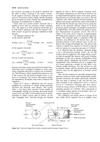
Figure 19.17 shows a laboratory test cell system plete assembly, in the configuration shown, is rated in
designed for evaluation of various nickel-hydrogen excess of 13.8 MN/m2. Prototype units have demon-
electrode and electrode stack designs. The system strated an energy density of 60 W h/kg at a maximum
offers a very heavy-duty pressure vessel capable of operating pressure of 3.5 kN/m2. This corresponds to
withstanding virtually any pressure developed during a volumetric energy density of 67 W h/dm3 and a vol-
system tests, and offers a convenient means of instru- umetric capacity of 55 Ah/dm3.
mentation to obtain various data of interest. In this The cylindrical cell design shown in Figure 19.18
case ‘pineapple slice’ electrode designs are stacked also yields 50Ah capacity, but at a slightly lower
Gas port Positive terminal
(semipermeable Spiral-wound
membrane) cell stack
Gas port
(semipermeable
membrane)
Negative terminal
Stack components
Gas volume macer Plastic cell case
Figure 19.17 Test cell of Eagle Picher nickel-hydrogen battery (Courtesy of Eagle Picher)