
Page 251 - Battery Reference Book
P. 251
Nickel-hydrogen and silver-hydrogen secondary batteries 19/17
Restrained single pressure vessel battery in nickel-hydrogen sys-
surface tem design.
This leads to an interesting design modification in
the metal-hydrogen system. If each cell is designed
with an excess of positive material, the cell will be gas
limited on discharge and all cells in the series string
will be exhausted at exactly the same time. This feature
would allow batteries to be discharged to a very low
voltage without concern for one or more cells dropping
out before the rest of the group. A metal-hydrogen cell
is capable, however, of operating in reversal without
degradation and prevention of this type of failure mode
does not carry the same impact as it would in current
secondary systems.
Figure 19.18 Prismatic spheroid cell design of Eagle Picher Other advantages of this design include the relia-
nickel-hydrogen battery, 20A h capacity (Courtesy of Eagle
Picher) bility and economics of the use of a single pressure
vessel for a battery. In addition, the internal cells,
which are not required to be sealed or to withstand
energy density of approximately 59 W fig. The cylin- pressure, may be of simple design and fabricated with
drical cell design is a self-contained pressure vessel cheaper materials. Individual cells will not require the
whereas the prismatic spheroid design requires partial relatively expensive ceramic-to-metal seals.
support from the battery structure. The energy density of the common pressure vessel
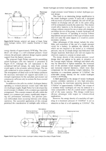
The proposed Eagle Picher concept for assembling design does not appear to be quite as attractive as
nickel-hydrogen cells into batteries is presented in the concept might indicate. Although individual cells
Figure 19.19. Although the cell represented is the may be fabricated of lighter materials. the increased
cylindrical half-cell design, the same basic concept size of the pressure vessel requires greater strength
would apply to the prismatic spheroid design. The ten and increased material thickness, which more than
cells connected in series produce a 12 V, 3 Ah system. compensate for the preceding weight reduction. For
The arrangement of these cells in the battery produces operation at a maximum pressure of 3.51cN/m2, the
the necessary individual cell support and results in a achievable energy density for the nickel-hydrogen
strength requirement for the end-plate and retainer rod system is 60 W hkg.
components sufficient only to restrain the force exerted A third approach to the design of nickel-hydrogen
by one cell. systems considers operation at very high pressures.
In addition to the cells in a nickel-hydrogen battery By increasing the maximum operating pressure from
operating as isolated pressure vessels each with their 3.5kN/m2 to approximately 14MN/m2, the volume of
own hydrogen supply, Eagle Picher have developed the a modular metal-hydrogen cell may be reduced to a
novel concept OC a battery with a common gas manifold value comparable to that of a sealed nickel-cadmium
arrangement. This concept connects all cells within the cell of the same capacity. This design would have
battery to a common gas source, significantly improv- obvious advantages with respect to volume-critical
ing cell performance uniformity, and prevents pres- applications.
sure differentials from occuning between cells during However, the energy density of a modular cell oper-
operation. The successful application of this concept ating at a maximum pressure of 14MN/m2 is not as
permitted the consideration of multiple cells within a attractive as that of a cell operating at 3.5 lcN/m2. The
Gas spacers
Positive terminal Nickel-hydrogen Negative terminal
(compression seal) 1 cells (total of 10) I
\ I36.Ocrn. I
Spherical ‘TIG weld Inteicell Stainles’s steel
end plates connector battery container
Figure 19.19 Eagle Picher nickel-hydrogen battery design (Courtesy of Eagle Picher)