
Page 248 - Battery Reference Book
P. 248
19/14 Nickel batteries
B P 0 N
+
C .- I m m
m
E ._
6 E
Y 6
m c
F
W
2 e - P
0 - t w t 6
100- ;; ;;
90- 3 3 100
80- 7 90
70- $ $ 80
60- n n
m
'B 50 - 70
40 c m 60
30 '2 50
20 40
10 30
0 20
A B C D E F
Design 10
0
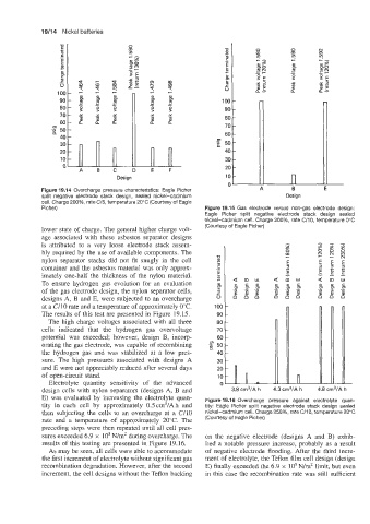
Figure 19.14 Overcharge pressure characteristics: Eagle Picher
split negative electrode stack design, sealed nickel-cadmium Design
cell. Charge 200%, rate C/5, temperature ZO'C (Courtesy of Eagle
Picher) Figure 19.15 Gas electrode versus non-gas electrode design:
Eagle Picher split negative electrode stack design sealed
nickel-cadmium cell. Charge ZOO%, rate C/10, temperature 0°C
lower state of charge. The general higher charge volt- (Courtesy of Eagle Picher)
age associated with these asbestos separator designs
is attributed to a very loose electrode stack assem-
bly required by the use of available components. The
nylon separator stacks did not fit snugly in the cell
container and the asbestos material was only approx-
imately one-half the thickness of the nylon material.
To ensure hydrogen gas evolution for an evaluation a m w
of the gas electrode design, the nylon separator cells,
designs A, B and E, were subjected to an overcharge
at a C/10 rate and a temperature of approximately 0°C.
The results of this test are presented in Figure 19.15.
The high charge voltages associated with all three
cells indicated that the hydrogen gas overvoltage
potential was exceeded; however, design B, incorp-
orating the gas electrode, was capable of recombining
the hydrogen gas and was stabilized at a low pres-
sure. The high pressures associated with designs A
and E were not appreciably reduced after several days
of open-circuit stand.
Electrolyte quantity sensitivity of the advanced
design cells with nylon separators (designs A, B and
E) was evaluated by increasing the electrolyte quan- Figure 19.16 Overcharge pressure against electrolyte quan-
tity in each cell by approximately 0.5cm3/Ah and tity: Eagle Picher split negative electrode stack design sealed
then subjecting the cells to an overcharge at a C/10 nickel-cadmium cell. Charge 250%, rate C/10, temperature 20°C
rate and a temperature of approximately 20°C. The (Courtesy of Eagle Picher)
preceding steps were then repeated until all cell pres-
sures exceeded 6.9 x lo5 N/mz during overcharge. The on the negative electrode (designs A and B) exhib-
results of this testing are presented in Figure 19.16. ited a notable pressure increase, probably as a result
As may be seen, all cells were able to accommodate of negative electrode flooding. After the third incre-
the first increment of electrolyte without significant gas ment of electrolyte, the Teflon film cell design (design
recombination degradation. However, after the second E) finally exceeded the 6.9 x lo5 N/m2 limit, but even
increment, the cell designs without the Teflon backing in this case the recombination rate was still sufficient