
Page 283 - Battery Reference Book
P. 283
24/6 Lithium batteries
Intercell electrolyte to flow. The movement of the cutter is
insulation Activation accomplished by the turning of an external screw (7),
Activation
manifold which is accessible in the base of the battery. The
Single / , Batterv
cutter section and the screw mechanism are isolated
from each other by a small collapsible metal cup (9),
which is hermetically sealed between the two sections.
This prevents external electrolyte leakage. The mani-
fold section is a series of small non-conductive plastics
tubes (10) connected at one end to the central cylinder
(4) and to each of the individual cells at the other end.
The long length and small cross-sectional area of the
tubes minimize intercell leakage losses during the time
that electrolyte is present in the manifold structure.
Using the lithium-sulphur dioxide system, four
individual cells are required to achieve the voltage
range desired for the total battery. The number of
cells is, of course, adjustable with minor modification
to meet a wide range of voltage needs. Each cell
contains flat circular anodes and cathodes, which are
separately wired in parallel to achieve the individual
cell capacity and plate area needed for a given set
of requirements. The components, with intervening
separators, are alternately stacked around the cell
centre tube, after which the parallel connections are
made. The cells are individually welded about the inner
tube and outer perimeter to form hermetic units ready
for series stacking within the battery. Connections
from the cells are made to external terminals, which
are located in the bottom bulkhead of the battery.
\' \ ' top Figure 24.7 is a photograph of the major battery
'
Battery
Freon backfil I Electrolyte Manifold bulkhead components before assembly. The components shown
volume storage bellows diaphragm are fabricated primarily from 321 stainless steel, and
the construction is accomplished with a series of TIG
20,60, 100 A h
battery cross-section welds.
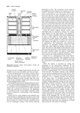
When the battery is activated by cutting the
Figure 24.4 Honeywell reserve lithium-sulphur dioxide cell diaphragm in the intermediate bulkhead, all the
(Courtesy of Honeywell)
liquid stored in the reservoir does not enter the cell
compartments. The amount of liquid initially placed in
driving force for eventual liquid transfer into the cell the cells is approximately 70% of the total contained
chamber section once the battery has been activated. in the reservoir. The balance remains in the manifold
In the remaining half of the battery volume, shown section and the uncollapsed portion of the bellows. The
at the top of the figure, is the centrally located elec- vapour pressure of the Freon gas behind the bellows
trolyte manifold and activation system housed in a maintains it in a collapsed position and therefore
15.88 mm diameter tubular structure plus the series in the liquid state. As discharge proceeds in the
stack of four toroidally shaped cells, which surround cells, generating free volume, the bellows continue to
the manifoldactivation system. collapse, forcing additional oxidant into the cells and
The manifold and cells are separated from the reser- permitting continued discharge. When the remaining
voir by an intermediate bulkhead. In the bulkhead there 30% of the oxidant enters the cells, the bellows
is a centrally positioned diaphragm of sufficiently thin have bottomed on the intermediate bulkhead, which
section that it can be pierced by the cutter contained relieves the Freon pressure from the cell section. This
within the manifold. In fabrication, the diaphragm permits vaporization of the sulphur dioxide, which
is assembled as part of the tubular manifold, which consequently isolates the cells from one another by
in turn is welded as a subassembly to the immediate vapour locks created in the small tubes. The activation
bulkhead. system, therefore, is dynamic in nature for the initial
Figure 24.6 is a more detailed cross-sectional view phases of the discharge life. For the concept to be
of the electrolyte manifold and activation system with practical. the hardware design must minimize intercell
the major components identified. The activating mech- leakage, maximize activator efficiency in terms of
anism consists of a cutter (5) which is manually moved liquid delivered, and ensure the maintenance of liquid
into the diaphragm, cutting it and thereby allowing flow during the early phase of discharge.