
Page 290 - Battery Reference Book
P. 290
Lithium-manganese dioxide primary batteries 24/13
iodine reduced fiorming additional lithium iodide. At sharpness of this ‘knee’ is a worst case approximation.
the anode: Under a 90 kQ load, at least 5 months should elapse
as cell impedance increases from 15 to 40kQ.
=
2~i 2~i+ + 2e- (24.11)
The open circuit voltage of the cell is 2.8 V and the
At the cathode (11 = 6): overall energy density is typically 150-25OmW h/g.
As the cell is discharged, lithium ions are transported
2Li’ + 2e- + P2VPnIz = P2VP (n-1) 12 + LiI (24.12) through the electrolyte to the cathode where iodide ions
are being formed. Thus, as the discharge continues, the
Net reaction: thickness of the electrolyte increases, until ultimately
2Li + P2VPnI2 = P2VP (n- 1) 12 + 2LiI (24.13) its impedance becomes the current limiting factor.
Two main types of medical pacemaker lithium-
The lithium iodide, which serves as both electrolyte iodine cells are manufactured:
and separator, aizcumulates as the cell is discharged
increasing the internal resistance. The result is an Type 1 Ribbed lithium anode to maximize anode area
and minimize impedance.
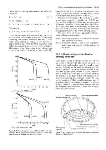
initial linear decline in voltage as can be seen in Type 2 Pelletized cathode to reduce cell impedance
Figure 24.15. Later, when the P2VP loses most of its and reduce migration of cathode material to
iodine, the cathode itself begins to rise in resistance.
This results in the ‘knee’ seen in the voltage-time the anode.
curves of pacemaker cells shown in Figure 24.15. The
24.6 Lithium-manganese dioxide
primary batteries
Some details on the construction of this type of cell
are shown in Figure 24.16. The current collector is a
sheet of perforated stainless steel. The stainless steel
top cap functions as the negative terminal and the
stainless steel cell can as the positive terminal of the
cell. The polypropylene closure is highly imperme-
able to water vapour and prevents moisture entering
the cell after it has been sealed. The separator is of
non-woven polypropylene cloth and contains the elec-
trolyte, a solution of lithium perchlorate in a mixture of
propylene carbonate and dimethoxyethane. The lithium
negative electrode is punched from sheet lithium and
2 4 6 8 10 12 14 16 the manganese dioxide cathode is made from a highly
Years active electrolytic oxide.
(a) Voltage under 190 kR load
Current collector, Lithium negative electrode
2 4 6 8 10 12 14 16 18 \
I \
Years Manganese dioxide cathode
(b) Voltage under 90 kR load Stainless steel Separator containing electrolyte
cell can Polypropylene closure
Figure 24.15 Projescted performance of Catalyst Research Cor-
poration Lithiode TIM lithium-iodine cells based on 5 years’ test Figure 24.16 Construction of a lithium-manganese dioxide cell
data (Courtesy of Catalyst Research Corporation) (Courtesy of Eagle Picher)