
Page 477 - Battery Reference Book
P. 477
47/10 Constant-current charging
Table 47.2 Technical specification of Nife Jungner sealed nickel-cadmium cells
Cell type KR 15/51 KR 23/43 KR 27/50 KR 35/62 KR 35/92
Nominal capacity (Ah) (5 h rate Cg at 25 & 5°C to 0.40 1.1 1.6 3.6 5.6
end-voltage 1 V)
Current on discharge (mA) (0.2Cg A) 80 220 320 720 1120
Dimensions
Diameter (mm) 14.5 22.7 26.0 33.2 33.2
Height (mm) 50.3 42.2 48.0 59.5 89.0
Weight, approx. (g) 20 45 65 140 210
Energy content (average discharge voltage with discharge at
5h current, 0.2CA, is 1.2V)
W Wcell 0.48 1.32 1.92 4.32 6.72
wmg 24 29 30 31 32
W Wdm3 65 81 78 86 90
Internal resistance (m i2) 90 27 22 13 11
Charging
Normal charging current 14-16h (mA) 50 120 200 400 600
Trickle charging minimum current (mA) 20 45 75 150 250
Temperature range From 0 to 40"C, preferably normal room temperature
Discharge
Maximum recommended continuous discharge current (A) 1.5 5 8 15 20
Maximum recommended discharge current for 5 (A) 7 15 20 50 80
Temperature range From -40 to +40°C
Storage In charged or discharge condition: use a cool storage
place, preferably with temperature lower than 15°C
Terminal arrangement:
Cell type CF, drawing No. 90-51400 90-51405 90-52813 90-51411 90-51417
Cell type HH, drawing No. 90-51401 90-51406 90-52814 90-51412 90-51418
Cell type HB, drawing No. 90-51402 90-51407 90-52815 90-51413 90-51419
Batteries with even number of cells, drawing No. - 90-52359 90-53536 90-52357 90-52355
Batteries with odd number of cells, drawing No. - 90-52360 90-53537 90-52358 90-52356
Corresponding dry cell R6 or AA Sub C R14 or C R20 or D -
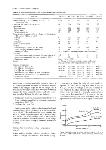
temperature exceeding permissible operating limits. It a maximum at about the fully charged condition.
is obviously possible that cells and batteries that are Figure 47.8 shows that at very low rates of charge
already fully charged might be put on charge, and a (O.lCs A) the rise of voltage at the end of charge is
preliminary discharge is therefore necessary. One hour very small; on the other hand at rapid rates (CgA to
chargers for these standard batteries and cells (avail- 2C5 A) it is quite large. It is generally accepted that a
able from SAFT) have the following features: charge rate at least equal to Cs A is necessary for the
end-of-charge voltage rise to be sufficiently sharp and
1. Preliminary discharge by connecting the battery to a reproducible and thus to serve as a signal to detect the
fixed resistance calculated to discharge a maximum
capacity of 0.6Cs Ah.
2. Recharge in 1 h at Cg A.
1.70-
Rapid charge for limited time of cylindrical cells and 2 C, A, 2.4 A
standard batteries is applicable only in the temperature 1.60 -
range 10-40°C. For cylindrical cells and standard bat- I
>
teries of capacities greater than 1.8 A h, no overcharge
at a rate of CgA is acceptable, and it is necessary to
consider a parameter other than time for the 1 h charge
of cells and batteries having an unknown initial state
of charge.
1.30 L/ I I I
0 50 100 150
Voltage-time control and voltage-temperature Capacity charged (% C,)
control
Figure 47.8 Cell voltage at various charging rates at 25°C for a
Sealed nickel-cadmium cells and batteries on charge SAFT VR 1.2 RR (1.2 A h) sealed nickel-cadmium cell (Courtesy
exhibit a voltage characteristic that passes through of SAFT)