
Page 153 - Bebop to The Boolean Boogie An Unconventional Guide to Electronics Fundamentals, Components, and Processes
P. 153
134 Chapter Twelve
State Tables
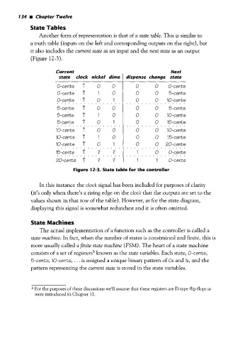
Another form of representation is that of a state table. This is similar to
a truth table (inputs on the left and corresponding outputs on the right), but
it also includes the current state as an input and the next state as an output
(Figure 12-3).
Current Next
state clock nickel dime I dispense change state
0-cents 'T o o 0 0 0-cents
0-cents 1' I 0 0 0 5-cents
5-cents + o o 0 0 10-cents
1'
1
0-cents
................ ................
o
0
0
5-cents
5-cents 1' 1 0 0 0 10-cents
5-cents 1' o 1 0 0 15-cents
................ ................
~o-cents 1; o o 0 0 10-cents
10-cents 1' I 0 0 0 15-cents
10-cents 1' o 1 0 0 20-cents
15-cents r ? ? 1 0 0-cents
................ ................
................ ................
20-cents f ? ? 1 1 0-cents
Figure 12-3. State table for the controller
In this instance the clock signal has been included for purposes of clarity
(it's only when there's a rising edge on the clock that the outputs are set to the
values shown in that row of the table). However, as for the state diagram,
displaying this signal is somewhat redundant and it is often omitted.
State Machines
The actual implementation of a function such as the controller is called a
state machine. In fact, when the number of states is constrained and finite, this is
more usually called a finite state machine (FSM) . The heart of a state machine
consists of a set of registers3 known as the state variables. Each state, 0-cents,
5-cent5, IO-cents, ... is assigned a unique binary pattern of Os and Is, and the
pattern represenring the current state is stored in the state variables.
3 For the purposes of these discussions we'll assume that these registers are D-type flip-flops as
were introduced in Chapter 1 1.