
Page 150 - Bebop to The Boolean Boogie An Unconventional Guide to Electronics Fundamentals, Components, and Processes
P. 150
State Diagrams, State
Tables, and State Machines
Consider a coin-operated machine that accepts nickels and dimes’ and,
for the princely sum of fifteen cents, dispenses some useful article called a
“gizmo” that the well-dressed man-about-town could not possibly be without.
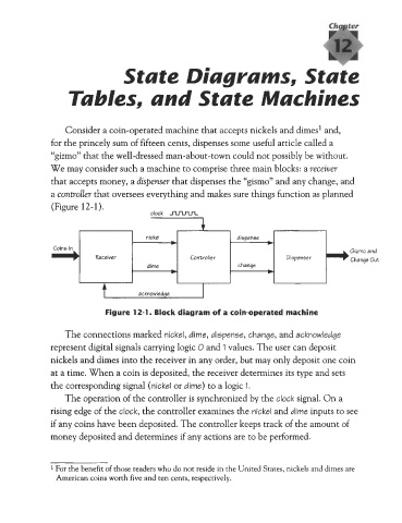
We may consider such a machine to comprise three main blocks: a receiver
that accepts money, a dispenser that dispenses the “gismo” and any change, and
a controller that oversees everything and makes sure things function as planned
(Figure 12-1).
nickel dispense
b b
Colne In
Gizmo and
Receiver Controller Dispenser Change Out
dime change
b b
Figure 12-1. Block diagram of a coin-operated machine
The connections marked nickel, dime, dispense, change, and acknowledge
represent digital signals carrying logic 0 and 1 values. The user can deposit
nickels and dimes into the receiver in any order, but may only deposit one coin
at a time. When a coin is deposited, the receiver determines its type and sets
the corresponding signal (nickel or dime) to a logic 1.
The operation of the controller is synchronized by the clock signal. On a
rising edge of the clock, the controller examines the nickel and dime inputs to see
if any coins have been deposited. The controller keeps track of the amount of
money deposited and determines if any actions are to be performed.
1 For the benefit of those readers who do not reside in the United States, nickels and dimes are
American coins worth five and ten cents, respectively.