
Page 148 - Bebop to The Boolean Boogie An Unconventional Guide to Electronics Fundamentals, Components, and Processes
P. 148
Using Primitive Logic Functions to Build More Complex Functions w 129
0-type flip-flop data
m
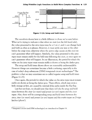
Figure 11-24. Setup and hold times
The waveform shown here is a little different to those we’ve seen before.
What we’re trying to indicate is that when we start (on the left-hand side),
the value presented to the data input may be a 0 or a 1, and it can change back
and forth as often as it pleases. However, it must settle one way or the other
before the setup time; otherwise when the active edge occurs on the clock we
can’t guarantee what will happen. Similarly, the value presented to the data
input must remain stable for the hold time following the clock, or once again we
can’t guarantee what will happen. In our illustration, the period for which the
value on the data input must remain stable is shown as being the darker gray.
The setup and hold times shown above are reasonably understandable.
However things can sometimes become a little confusing, especially in the
case of today’s deep submicron (DSM) integrated circuit technologies.’ The
problem is that we may sometimes see so-called negative setup and hold times
(Figure 11-25).
Once again, the periods for which the value on the data input must remain
stable are shown as being the darker gray. These effects, which may seem a
little strange at first, are caused by internal delay paths inside the flip-flop.
Last but not least, we should note that there will also be setup and hold
times between the clear (or reset) and preset (or set) inputs and the clock
input. Also, there will be corresponding setup and hold times between the
data, clear (or reset) and preset (or set) inputs and the enable input on D-type
latches (phew!).
9 Integrated circuits (and DSM technologies) are introduced in Chapter 14.