
Page 144 - Bebop to The Boolean Boogie An Unconventional Guide to Electronics Fundamentals, Components, and Processes
P. 144
Using Primitive Logic Functions to Build More Complex Functions 125
4. PI
4 [I1
I I I
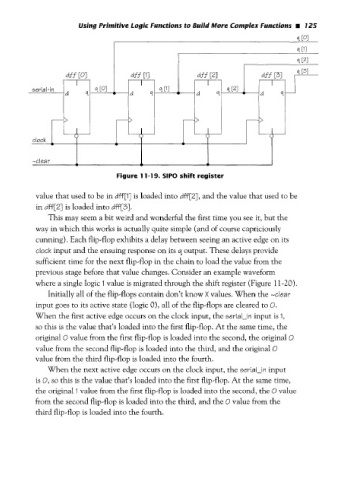
Figure 11-19. SIP0 shift register
value that used to be in dff[l] is loaded into dff[Z], and the value that used to be
in dff [Z] is loaded into dff [3].
This may seem a bit weird and wonderful the first time you see it, but the
way in which this works is actually quite simple (and of course capriciously
cunning). Each flip-flop exhibits a delay between seeing an active edge on its
clock input and the ensuing response on its s, output. These delays provide
sufficient time for the next flip-flop in the chain to load the value from the
previous stage before that value changes. Consider an example waveform
where a single logic I value is migrated through the shift register (Figure 11-20),
Initially all of the flip-flops contain don’t know X values. When the -clear
input goes to its active state (logic 0)’ all of the flip-flops are cleared to 0.
When the first active edge occurs on the clock input, the serial-in input is I,
so this is the value that’s loaded into the first flip-flop. At the same time, the
original O value from the first flip-flop is loaded into the second, the original O
value from the second flip-flop is loaded into the third, and the original O
value from the third flip-flop is loaded into the fourth.
When the next active edge occurs on the clock input, the 5eriaI-in input
is 0, this is the value that’s loaded into the first flip-flop. At the same time,
so
the original 1 value from the first flip-flop is loaded into the second, the 0 value
from the second flip-flop is loaded into the third, and the 0 value from the
third flip-flop is loaded into the fourth.