
Page 141 - Bebop to The Boolean Boogie An Unconventional Guide to Electronics Fundamentals, Components, and Processes
P. 141
122 rn Chapter €le ven
1 _-_-__ I
I
data I I I I
I
0- 1 I I
1 ------------
clock
0-
1
01 xxxxxx
0
1
-4, xxxxxxl
0
Time
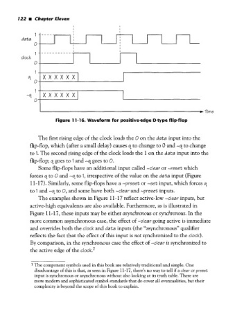
Figure 1 1-1 6. Waveform for positive-edge D-type flip-flop
The first rising edge of the clock loads the 0 on the data input into the
flip-flop, which (after a small delay) causes 9 to change to 0 and -9 to change
to 1. The second rising edge of the clock loads the 1 on the data input into the
flip-flop; q goes to I and -9 goes to 0.
Some flip-flops have an additional input called -clear or -reset which
forces 9 to 0 and -4 to 1, irrespective of the value on the data input (Figure
11-17). Similarly, some flip-flops have a -preset or -set input, which forces q
to I and -01 to 0, and some have both -clear and -preset inputs.
The examples shown in Figure 11-17 reflect active-low -clear inputs, but
active-high equivalents are also available. Furthermore, as is illustrated in
Figure 11-17, these inputs may be either asynchronous or synchronous. In the
more common asynchronous case, the effect of -clear going active is immediate
and overrides both the clock and data inputs (the ((asynchronous” qualifier
reflects the fact that the effect of this input is not synchronized to the clock).
By comparison, in the synchronous case the effect of -clear is synchronized to
the active edge of the clock.7
7 The component symbols used in this book are relatively traditional and simple. One
disadvantage of this is that, as seen in Figure 11-17, there’s no way to tell if a clear or preset
input is synchronous or asynchronous without also looking at its truth table. There are
more modem and sophisticated symbol standards that do cover all eventualities, but their
complexity is beyond the scope of this book to explain.