
Page 138 - Bebop to The Boolean Boogie An Unconventional Guide to Electronics Fundamentals, Components, and Processes
P. 138
-u- NOR 1 19
Using Primitive Logic Functions to Build More Complex Functions
D latch
m
I
f I AND I
enable
5
NOR
enable
0 AND
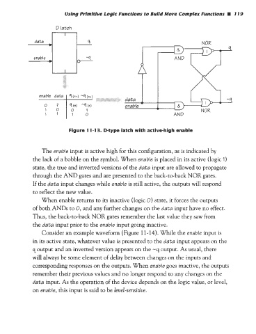
Figure 1 1-1 3. D-type latch with active-high enable
The enable input is active high for this configuration, as is indicated by
the lack of a bobble on the symbol. When enable is placed in its active (logic I)
state, the true and inverted versions of the data input are allowed to propagate
through the AND gates and are presented to the back-to-back NOR gates.
If the data input changes while enable is still active, the outputs will respond
to reflect the new value.
When enable returns to its inactive (logic 0) state, it forces the outputs
of both ANDs to 0, and any further changes on the data input have no effect.
Thus, the back-to-back NOR gates remember the last value they saw from
the data input prior to the enable input going inactive.
Consider an example waveform (Figure 1 1 - 14). While the enable input is
in its active state, whatever value is presented to the data input appears on the
q output and an inverted version appears on the -q output. As usual, there
will always be some element of delay between changes on the inputs and
corresponding responses on the outputs. When enable goes inactive, the outputs
remember their previous values and no longer respond to any changes on the
data input. As the operation of the device depends on the logic value, or level,
on enable, this input is said to be level-sensitive.