
Page 154 - Bebop to The Boolean Boogie An Unconventional Guide to Electronics Fundamentals, Components, and Processes
P. 154
State Diagrams, State Tables, and State Machines 135
The two most common forms of synchronous, or clocked, state machines
are known as Moore and Mealy machines after the men who formalized them.
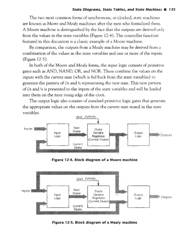
A Moore machine is distinguished by the fact that the outputs are derived only
from the values in the state variables (Figure 12-4). The controller function
featured in this discussion is a classic example of a Moore machine.
By comparison, the outputs from a Mealy machine may be derived from a
combination of the values in the state variables and one or more of the inputs
(Figure 12-5).
In both of the Moore and Mealy forms, the input logic consists of primitive
gates such as AND, NAND, OR, and NOR. These combine the values on the
inputs with the current state (which is fed back from the state variables) to
generate the pattern of Os and Is representing the next state. This new pattern
of OS and IS is presented to the inputs of the state variables and will be loaded
into them on the next rising edge of the clock.
clock -
The output logic also consists of standard primitive logic gates that generate
the appropriate values on the outputs from the current state stored in the state
variables.
Inputs
output5
Figure 12-4. Block diagram of a Moore machine
Input5
output5
Figure 12-5. Block diagram of a Mealy machine