
Page 447 - 02. Subyek Computer Aided Design - Beginner’s Guide to SOLIDWORKS 2019- Level 1 by Alejandro Reyes
P. 447
Detail Drawing
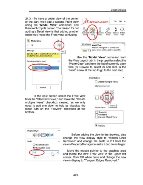
21.3. -To have a better view of the center
~
of the part, we'll add a second Front view ;jS SOLIDWORKS File Edit Vi
using the "Model View" command, and
then we'll crop its center. The reason for not ~= , I~J o o:~ ~ CA
.#~
FR
adding a Detail view is that adding another
Stand oj ected Auxiliary Section Detail
circle may make the Front view confusing. 3 Vie View View View View
l~j Model View
----·- · - - ·--'-
View layo
.../ X
Adds an orthogonal or named view
--~1
Message 1 r:JJ [ R based on an existing part or assembly.
Select a part or assembly from which to
create the view, then click Next.
Use the "Model View" command from
the View Layout tab, in the properties select the
Part/Assembly to Insert
'Worm Gear' part from the list of currently open
files (or Browse to select it) and click in the
"Next" arrow at the top to go to the next step.
0 Orientation
0 Create multiple views
Browse... J Standard view s:
[
In the next screen select the Front view
from the "Standard views," and leave the "Create
multiple views" checkbox cleared, as we only
need to add one view; to help us visualize the •Front
lore view s:
result turn on the "Preview" checkbox at the
bottom. - *Dimetric
- *Trimetric
: Current Model View
~ Preview
Display Style
Before adding the view to the drawing, also
change the view display style to "Hidden Lines
Scale Removed" and change the scale to 2:1 from the
0 Use sheet scale view's PropertyManager to make it two times larger.
@ Use custom scale
Move the mouse pointer to the graphics area
v
and locate the new Front view in the upper left
2:1 corner. Click OK when done and change the new
view's display to "Tangent Edges Removed."
449