
Page 536 - 02. Subyek Computer Aided Design - Beginner’s Guide to SOLIDWORKS 2019- Level 1 by Alejandro Reyes
P. 536
Assembly Modeling
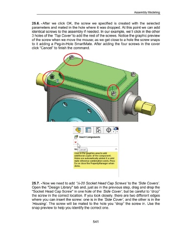
25.6. -After we click OK, the screw we specified is created with the selected
parameters and mated in the hole where it was dropped. At this point we can add
identical screws to the assembly if needed. In our example, we'll click in the other
3 holes of the 'Top Cover' to add the rest of the screws. Notice the graphic preview
of the screw when we move the mouse; as we get close to a hole the screw snaps
to it adding a Peg-in-Hole SmartMate. After adding the four screws in the cover
click "Cancel" to finish the command .
..... ..... .......
---- ...........
....... ..
-.. _
.........
........ ..
-.. _
....
.
•
!'
•
•
f!1 1nsert Components
Click in the graphics area to add
additional copies of the component.
Mates are automatically added if a valid
mate reference combination exists. Press
Esc or close the PropertyManager when
done.
25.7. -Now we need to add ':4-20 Socket Head Cap Screws' to the 'Side Covers'.
Open the "Design Library" tab and, just as in the previous step, drag and drop the
"Socket Head Cap Screw" in one hole of the 'Side Cover', but be careful to "drop"
the screw in the correct location. If you look closely, there are two different edges
where you can insert the screw: one is in the 'Side Cover', and the other is in the
'Housing'. The screw will be mated to the hole you "drop" the screw in. Use the
snap preview to help you identify the correct one.
541