
Page 538 - 02. Subyek Computer Aided Design - Beginner’s Guide to SOLIDWORKS 2019- Level 1 by Alejandro Reyes
P. 538
Assembly Modeling
25.9. -Instead of manually adding the rest of the screws, we'll make a component
pattern using the first screw. Just like a feature pattern in a part, we can add linear
or circular component patterns in an assembly, but in this case we are going to
use a different type of pattern that allows us to make a component pattern to match
a part's feature pattern. Think of it this way: we
make a pattern of bolts to match the pattern of ~
holes in the 'Side Cove'. This way, IF the pattern , Linear Smart Move
Show
of holes changes (more or less holes), the Component Fasteners Component Hidden
Pattern
Components
pattern of screws in the assembly updates to
match. In the Assembly tab, select "Pattern ... -
Driven Component Pattern" from the drop so ~~ Linear Component Pattern
down menu in the "Linear Component
Pattern" or the menu "Insert, Component D
Pattern, Pattern Driven." C!C!
§a Curve Driven Component Pattern
~ Chain Component Pattern
GJiiJ Mirror Components
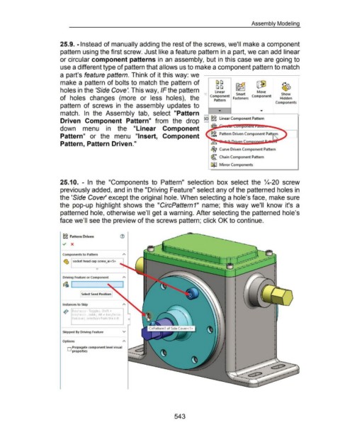
25.1 0. - In the "Components to Pattern" selection box select the %-20 screw
previously added, and in the "Driving Feature" select any of the patterned holes in
the 'Side Cover' except the original hole. When selecting a hole's face, make sure
the pop-up highlight shows the "CircPattern1" name; this way we'll know it's a
patterned hole, otherwise we'll get a warning. After selecting the patterned hole's
face we'll see the preview of the screws pattern; click OK to continue.
~~ Pattern Driven ®
Components t o Pattern
~ socket head cap screw_ai <S>
Driving Feature or Component
~ '"-----__;:
Select Seed Position
Instances to Skip
o!• BoX/lasso- Toggles, Shift+
0
0
boX/lasso- Adds, Alt + boX/lasso-
Removes, selection from the list.
Skipped By Driving Feature v
Options
D Propagate component level visual
properties
543