Page 542 - 02. Subyek Computer Aided Design - Beginner’s Guide to SOLIDWORKS 2019- Level 1 by Alejandro Reyes
P. 542

Assembly Modeling


                                                      Configurations using Design Tables


                                                                        Previously we  covered  how to  make configurations  of parts  by  manually


                                                      suppressing  features  and  changing  dimensions.  Configuring  parts  using  this


                                                      technique may be adequate when we have 2, maybe 3 configurations and a couple


                                                      of configured features and/or dimensions, but it becomes very difficult to keep track


                                                      of  changes  in  the  different  configurations  when  we  have  5,  10,  20,  or  more


                                                      configurations with multiple features and dimensions.


                                                                        In  these  cases,  adding  a  Design  Table  is  the  best  way  to  manage


                                                      configurations.  A  Design  Table  is  an  Excel  file  embedded  in  (or  linked  to)  a


                                                      SOLIDWORKS  part  or  assembly  that  controls  dimension  values,  feature


                                                      suppression states, configuration names, custom file  properties, etc., allowing us


                                                      to easily manage all the configurations in a single table.


                                                                        The  use  of Design  Tables  in  SOLIDWORKS  2018  (Educational  version


                                                                        2018-2019)  requires  Microsoft  Excel  2010,  2013  or  2016.  No  other


                                                                        spreadsheet software is supported.


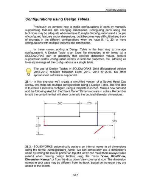
                                                      26.1. -In  this  exercise  we'll  create  a  simplified  version  of a  Socket  Head  Cap


                                                      Screw, and then add multiple configurations using a Design Table.  The first step


                                                      is to create a model to configure using a template in inches. Make a new part and


                                                      add the following sketch in the "Front Plane." Dimensions are in inches. Remember


                                                      to add the centerline that will allow us to add the doubled diameter dimensions .


                                                                                                                                                                                                                                           . 375
                                                                                            ....., ______________                                                                                               ~ ,.....--- .


                                                                           .250                                                                                                                          ......,


                                                      26.2. -SOLI DWORKS automatically assigns  an  internal  name to  all  dimensions


                                                      using  the  format  name@feature  name.  We  can  temporarily  see  a  dimension's


                                                      name by resting the mouse pointer on top of it, or we can make them always visible


                                                      (useful  when  making  design  tables)  using  the  menu  "View,  Hide/Show,


                                                      Dimension Names" or from the drop down View command  icon. The dimension


                                                      names in your case may be different from the book,  based on the order they are


                                                      added to the sketch.


                                                                                                                                                           547
   537   538   539   540   541   542   543   544   545   546   547