Page 535 - 02. Subyek Computer Aided Design - Beginner’s Guide to SOLIDWORKS 2019- Level 1 by Alejandro Reyes
        P. 535
     Beginner's Guide to SOLIDWORKS 2019- Level I
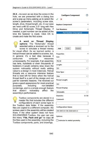
                                    25.5. -As soon as we drop the screw in the
                                                                                                                                                                          Configure Component
                                    hole,  we  are  presented  with  a  dialog  box
                                    and a pop-up menu asking us to select the                                                                                          X
                                    screw's  parameters,  including  screw size,
                                    length, drive, thread length, etc. In our case                                                                          Replace Component
                                    we need a #6-32 screw, 0.5" long with Hex
                                    Drive  and  Schematic  Thread  Display.  If                                                                             Part Numbers
                                    needed, a part number can be added at the
                                                                                                                                                                              Part Number Unassigned
                                    time  the  fastener  is  made.  Click  OK  to
                                    create and mate the first screw.
                                                       A  word  on  Thread  Display
                                                       options:  The  "Schematic"  thread
                                                       selected  adds a  revolved  cut to the
                                                       screw  to  simulate  a  thread  merely                                                               [ Add]                      Ed1t                     Delete
                                    for  visual  effect.  As  we  learned  earlier,  a
                                    helical thread can be added to a screw, but,
                                    in  general,  it's  a  bad  idea  because  it
                                    consumes                                     computer                                  resources
                                    unnecessarily. For example, if an assembly
                                    has  tens,  hundreds  or even  thousands  of
                                    fasteners  it would  certainly slow down  the
                                    system  noticeably  without  really  adding
                                    value to a design in most instances. Helical
                                    threads  are  a  resource  intensive  feature
                                    that is  best left for times  when  the  helical
                                    thread itself is a part of the design and  not
                                    just for cosmetic reasons. The revolved cut
                                    gives a good appearance for most practical
                                    purposes,                                 including                             non-detailed
                                    renderings, and is a simple enough feature
                                    that               doesn't                    noticeably                         affect                 the
                                    assembly's performance.
                                                     Toolbox components are stored in  a
                                                                                                                                                            Comment:
                                                     master file that includes the different
                                                     configurations of each screw type in                                                                                                                                                          I
                                    the  Toolbox  data  folder.  If  the  assembly
                                    files are copied to a different computer, the                                                                           Configuration Name:
                                    screws used in the assembly will be created
                                                                                                                                                           I HX-SHCS 0.138-32x0.5x0.5-S                                                            I
                                    there.  If the  other  system  does  not  have
                                    SOLIDWORKS Toolbox,  the  user can  use
                                                                                                                                                            Options
                                    the  menu  "File,  Pack and go" to copy all
                                    the files used in the assembly, including the                                                                          D Auto size to mated geometry
                                    Toolbox components, parts, and drawings.
                                                                                                                                         540


