
Page 552 - 02. Subyek Computer Aided Design - Beginner’s Guide to SOLIDWORKS 2019- Level 1 by Alejandro Reyes
P. 552
Assembly Modeling
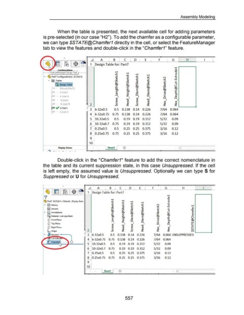
When the table is presented, the next available cell for adding parameters
is pre-selected (in our case "H2"). To add the chamfer as a configurable parameter,
we can type $STATE@Chamfer1 directly in the cell, or select the FeatureManager
tab to view the features and double-click in the "Chamfer1" feature .
. ://///////////////////////////////////////////////////////////////////////////////////////////////////.. ///////////////////////////////////////////////////////////////////////////.
%
0
~~f}i~~~lr· ~ A I B I c D E I F I G H l
., ~ -$ . ~ ~ 1 Design Table for: Part7
,_ ~ -
~
~
~
FeatureManager Design Tree ~
~
~ ~
... ~ Part7 Configuration(s) (0.25x0.5) ~ u
~ .... N
Q)
..,.. IS) Tables ~ ~ ~
~
u
~ (,/') ....
I6Jc: Design Table I ~ @J ~
Q)
~
~
~ Default [ Part7] ~ (,/')
~
@J
....
~X 6-32x0.5 ~ ro Q) ~
~
~ Q) ·- ro > c.
~ 0
t« - 6-32x0. 75 ~ ::I: 0 ~ Q)
~ I ~I I 0 0
I« - 10.32x0.5 ~ "'0 Q) "'0 I I
~
~ ro ~ ro X X .____ ___ _
~
I X 10-32x0.75 • 2 Q) u Q) Q) Q)
::I: (,/') ::I: ::I: ::I:
~ .; 0.25x0.5 0 3 6-32x0.5 0.5 0.138 0.14 0.226 7/64 0.064
~X 0.25x0.75 ~
~ 4 6-32x0.75 0.75 0.138 0.14 0.226 7/64 0.064
~ -
~ 5 10.32x0.5 0.5 0.19 0.19 0.312 5/32 0.09
~
~
~ 6 10-32x0.7 0.75 0.19 0.19 0.312 5/32 0.09
~ -
~
~ 7 0.25x0.5 0.5 0.25 0.25 0.375 3/16 0.12
~
~ -
~
~ 8 0.25x0.75 0.75 0.25 0.25 0.375 3/16 0.12
~
~
~ 9
~ -
~ 10
~--------------------- ~ ~--~ ~--~--------------------~--~~~----------~==
1
+
Dknlay States ~ ,. I Sheet1 1 ® I ~ I
-... ~ ....:..J_
."/'///,a////////~.('////////////////////////////////////////////////////////////////////////////////////;.9////////////////////////////////////////////////////////////////////////h
Double-click in the "Chamfer1" feature to add the correct nomenclature in
the table and its current suppression state, in this case Unsuppressed. If the cell
is left empty, the assumed value is Unsuppressed. Optionally we can type S for
Suppressed or U for Unsuppressed.
0
A 1 B C I D I E I F G I H
1 Design Table for: Part7
......
Q)
""0
~ Part7 (0.25x0.5< <Default> _Display State ...... ...... ,_
~
~ ....
~ f!$J History .... ~ N w
u
X
....
u
u
Q) ~ ....
I
fG'I Sensors ...:.:: Q) ....
V) ...:.:: Q) ~
~ I)J Annotations @J V) ...:.:: u
o- @J V) @J
~-o Material <not specified> E E @J
....
ro Q) ~
[lJ Front Plane Q) ro > a.
:I: 0 0 ,_ Q)
[;1 Top Plane I ;;I I 0 0
""0 ""0 I I
Q)
[lJ Right Plane cu ,_ ro X X
Q) u Q) Q) Q) ....._ ___ .
L Origin 2 :I: V) :I: :I: :I:
~ /b Revolve1 --- o 3 6-32x0.5 0.5 0.138 0.14 0.226 7/64 0.064 UNSUPPRESSED
-
'll::!'-Cut-Extrli .... ,,, 4 6-32x0.75 0.75 0.138 0.14 0.226 7/64 0.064
e At-;;1,__ __ 1 ~ 5 10.32x0.5 0.5 0.19 0.19 0.312 5/32 0.09
-
I~ c.h, :."1 ----- t 0
-
6 10-32x0.7 0.75 0.19 0.19 0.312 5/32 0.09
-
7 0.25x0.5 0.5 0.25 0.25 0.375 3/16 0.12
-
8 0.25x0.75 0. 75 0.25 0.25 0.375 3/16 0.12
-
9
-
10
I Sheet1 I (±)
557